WTEC II ELECTRONIC CONTROLS TROUBLESHOOTING MANUAL
1–6 Copyright © 1998 General Motors Corp.
GENERAL DESCRIPTION
1–6. CONTROL MODULE
(Figure 1–9)
The WT Series transmission control module contains a channel plate on which is mounted: the main valve body
assembly, the stationary-clutch valve body assembly, and the rotating-clutch valve body assembly. For valve
locations, refer to SIL 27-WT-93, Rev. A. Pulse width modulated solenoids are used in the valve bodies. The
rotating-clutch valve body assembly contains A (C1), B (C2), and F (lockup) solenoids, solenoid regulator valves
controlled by the solenoids, and the C3 pressure switch. The stationary-clutch valve body assembly contains C
(C3), D (C4), and E (C5) solenoids and solenoid regulator valves controlled by the solenoids and the C3
accumulator relay valve. The main valve body assembly contains G solenoid and the C1 and C2 latch valves
controlled by the solenoid, the main and lube regulator valves, the control main and converter regulator valves, and
the converter flow valve and exhaust backfill valves.
A temperature sensor (thermistor) is located in the internal wiring harness. Changes in sump fluid temperature are
indicated by changes in sensor resistance which changes the signal sent to the ECU (see chart in Section 6, Code 24).
The oil level sensor is required on all models with a shallow sump but is optional on other models. The oil level
sensor is a float-type device, mounted on the control module channel plate, which senses transmission fluid level by
electronically measuring the buoyancy forces on the float. The sensor operates on 5VDC supplied by the ECU.
The C3 pressure switch is mounted on the rotating-clutch valve body assembly and indicates when pressure exists
in the C3 clutch-apply passage. An accumulator/relay valve is in-line ahead of the C3 pressure switch and prevents
high frequency hydraulic pulses generated by the C3 solenoid from cycling the C3 pressure switch.
Also mounted in the control module is the turbine speed sensor for the MD/B 300/B 400 models. The turbine speed
sensor is directed at the rotating-clutch housing. (The turbine speed sensor on the HD/B 500 models is located on
the outside of the main housing.)
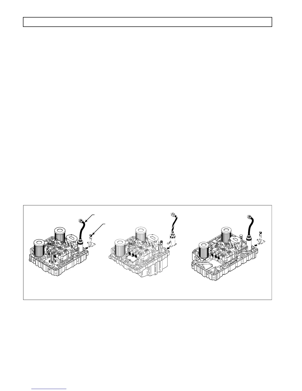
Figure 1–9. Control Module
V01591.02
MD/B 300/B 400 CONTROL MODULE MD 3070 CONTROL MODULE HD/B 500 CONTROL MODULE
UNITS PRODUCED
PRIOR TO 9/94
UNITS PRODUCED
9/94 – 12/97