Copyright © 1998 General Motors Corp. P–5
WTEC II ELECTRONIC CONTROLS TROUBLESHOOTING MANUAL
APPENDIX P — INPUT/OUTPUT FUNCTIONS
WARNING!
These schematics show the intended use of the specified controls features which
have been validated in the configuration shown. Any miswiring or use of these
features which differs from that shown could result in damage to equipment or
property, personal injury, or loss of life. ALLISON TRANSMISSION IS NOT
LIABLE FOR THE CONSEQUENCES ASSOCIATED WITH MISWIRING
OR UNINTENDED USE OF THESE FEATURES.
SHIFT SELECTOR TRANSITION
USES:
When two shift selectors are used, to select which one is active.
VARIABLES TO SPECIFY:
None
VOCATIONS:
Various
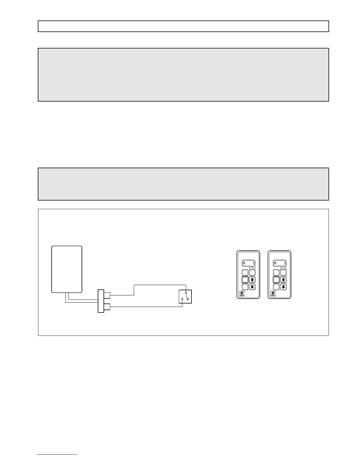
Figure P–5. Shift Selector Transition
WARNING!
If this function is enabled in the shift calibration, the function MUST be integrated
into the vehicle wiring. If the function is available in the shift calibration but will
not be used in the vehicle, it MUST be disabled in the calibration.
SELECTOR
1
DASH SWITCH
Open: Selector 1
Closed: Selector 2
V05010
SELECTOR
2
To switch between selector 1
and selector 2, transmission
must be in neutral and output
speed below 60 rpm.
When ECU is turned on,
active shift selector is
determined by current
switch position.
WIRE 161B
SIGNAL GROUND
WIRE 155
SHIFT SELECTOR
TRANSITION
R
N
D
MODE
MODE ON
SELECT MONITOR
SERVICE
R
N
D
MODE
MODE ON
SELECT MONITOR
SERVICE
ECU
VIW
CONNECTOR
13
9