WTEC II ELECTRONIC CONTROLS TROUBLESHOOTING MANUAL
P–6 Copyright © 1998 General Motors Corp.
APPENDIX P — INPUT/OUTPUT FUNCTIONS
WARNING!
These schematics show the intended use of the specified controls features which
have been validated in the configuration shown. Any miswiring or use of these
features which differs from that shown could result in damage to equipment or
property, personal injury, or loss of life. ALLISON TRANSMISSION IS NOT
LIABLE FOR THE CONSEQUENCES ASSOCIATED WITH MISWIRING
OR UNINTENDED USE OF THESE FEATURES.
AUXILIARY FUNCTION RANGE INHIBIT (STANDARD)
USES:
Prevents inadvertent range selection when auxiliary equipment is operating or prevents engagement of the
transmission unless brake pedal is depressed.
VARIABLES TO SPECIFY:
None
VOCATIONS:
Transit bus, school bus — auxiliary equipment input; various (brake pedal input)
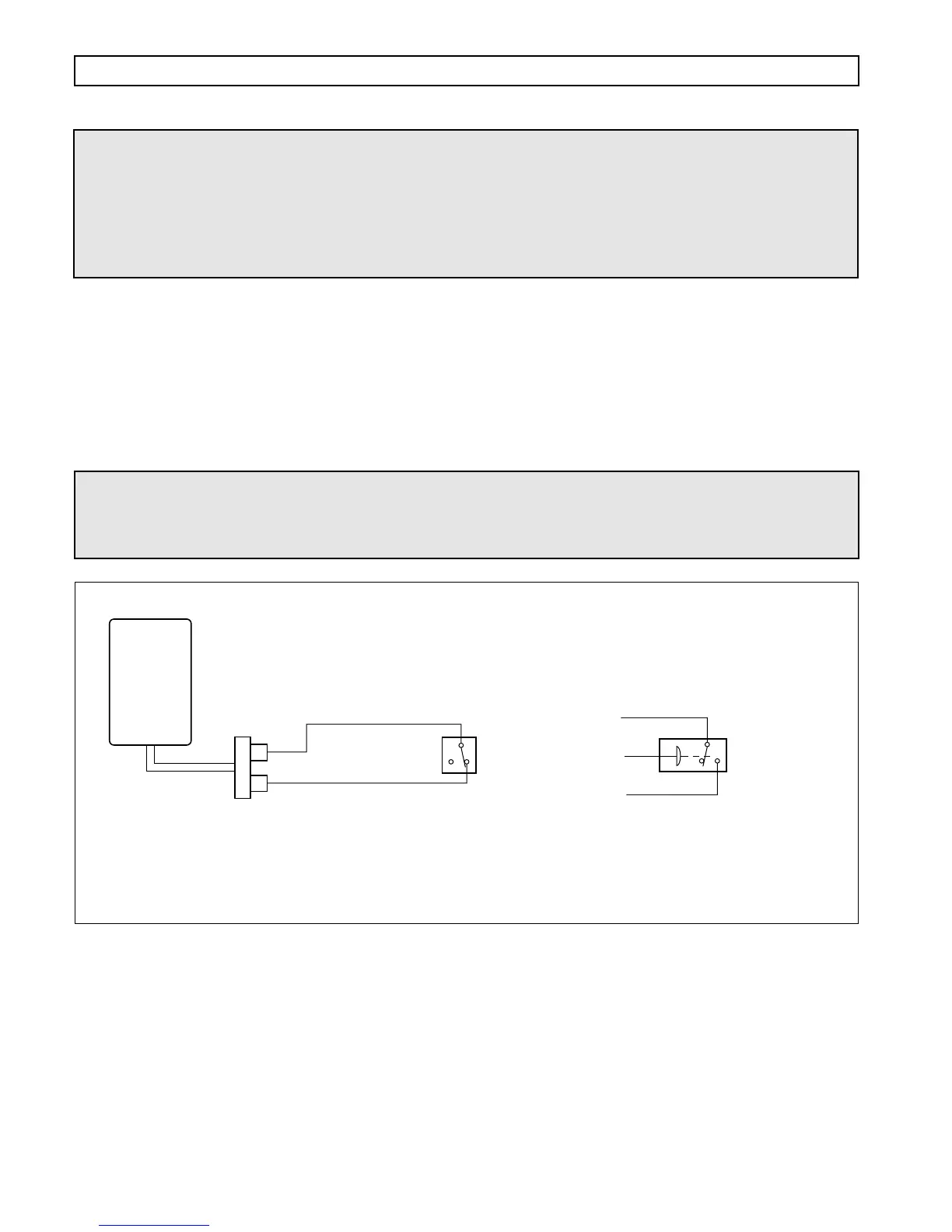
Figure P–6. Auxiliary Function Range Inhibit (Standard)
WARNING!
If this function is enabled in the shift calibration, the function MUST be integrated
into the vehicle wiring. If the function is available in the shift calibration but will
not be used in the vehicle, it MUST be disabled in the calibration.
– OR –
V05011
Switch is open
when auxiliary
equipment is
operating
Switch closes
when brakes
are applied
WIRE 161B
SIGNAL GROUND
WIRE 155
AUX. FUNCTION
RANGE INHIBIT (STD)
WIRE 161B
WIRE 155
NOTE: ECUs with this function activated must have wire 155
permanently connected to wire 161B if the function is not being used.
ECU
13
9
VIW
CONNECTOR
WARNING!
These schematics show the intended use of the specified controls features which
have been validated in the configuration shown. Any miswiring or use of these
features which differs from that shown could cause unintended selection of range
or other unpredictable operation resulting in damage to equipment or property,
personal injury, or loss of life. ALLISON TRANSMISSION IS NOT LIABLE
FOR THE CONSEQUENCES ASSOCIATED WITH MISWIRING OR
UNINTENDED USE OF THESE FEATURES.