Copyright © 1998 General Motors Corp. 8–17
GENERAL TROUBLESHOOTING OF PERFORMANCE COMPLAINTS
WTEC II ELECTRONIC CONTROLS TROUBLESHOOTING MANUAL
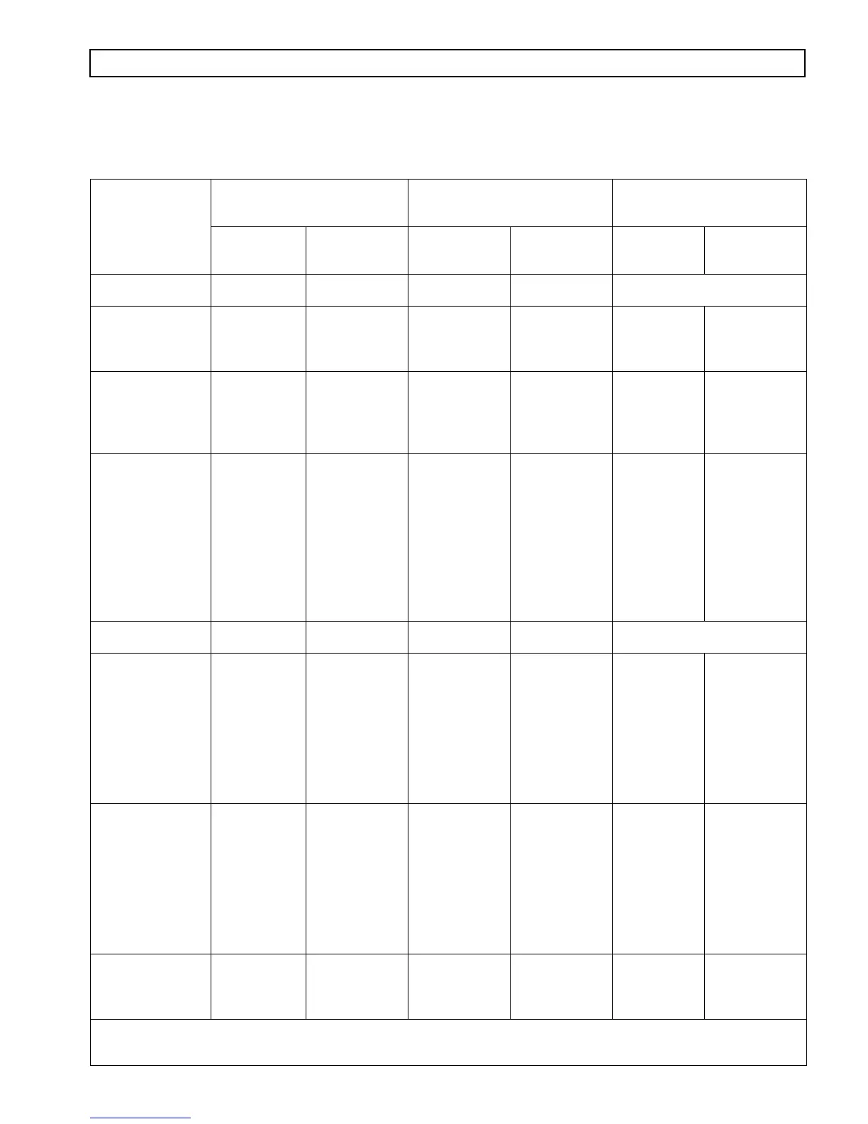
Table 8–2. Resistance Module Troubleshooting Data
Description
Resistance Check in
Resistance Module*
Voltage Signal** Wiring to Control Device
Terminals
Resistance
± 5%
% Retarder
Application
Voltage
± 0.2V
Device
Terminal
Wire Color
Auto Full On
A to C 12 K 100 3.6 No connections
Pressure Switch
Full On
High
A to C 32 K 0
100
1.1
3.6
A
B
White
Blue
3-Step E-10R
Bendix Pedal
A to C 32 K 0
32
58
100
1.1
1.9
2.8
3.6
A
B
C
D
Blue
Violet
White
Orange
6-Step Hand
Lever —
Off
Position 1
Position 2
Position 3
Position 4
Position 5
Position 6
A to C 32 K
0
16
28
48
65
84
100
1.1
1.5
1.9
2.3
2.8
3.2
3.6
+
1
2
3
4
5
6
White
Blue
Orange
Violet
Green
Yellow
Red
Auto
1
/
2
On
A to C 12 K 50 2.4 No connections
3 Pressure
Switches
—
Low
Medium
High
A to C 32 K
0
32
68
100
1.1
1.9
2.3
3.6
A
B
A
B
A
B
White
Blue
White
Orange
White
Violet
Auto
1
/
3
On
2 Pressure
Switches
Auto
Medium
High
A to C 21.4 K
32
68
100
1.9
2.8
3.6
A
B
A
B
White
Orange
White
Violet
Dedicated Pedal No Checks
Interface not
a resistance
module
0
100
0.7–1.2
3.4–3.5
A
B
C
Green
Yellow
White
* Resistance module must be disconnected from the wiring harness and retarder control devices.
** These voltages must be measured between terminals A and B.
ELECTRONIC AND HYDRAULIC TROUBLESHOOTING