6
Subject to change without notice | 83030100dUK | ait-deutschland GmbH
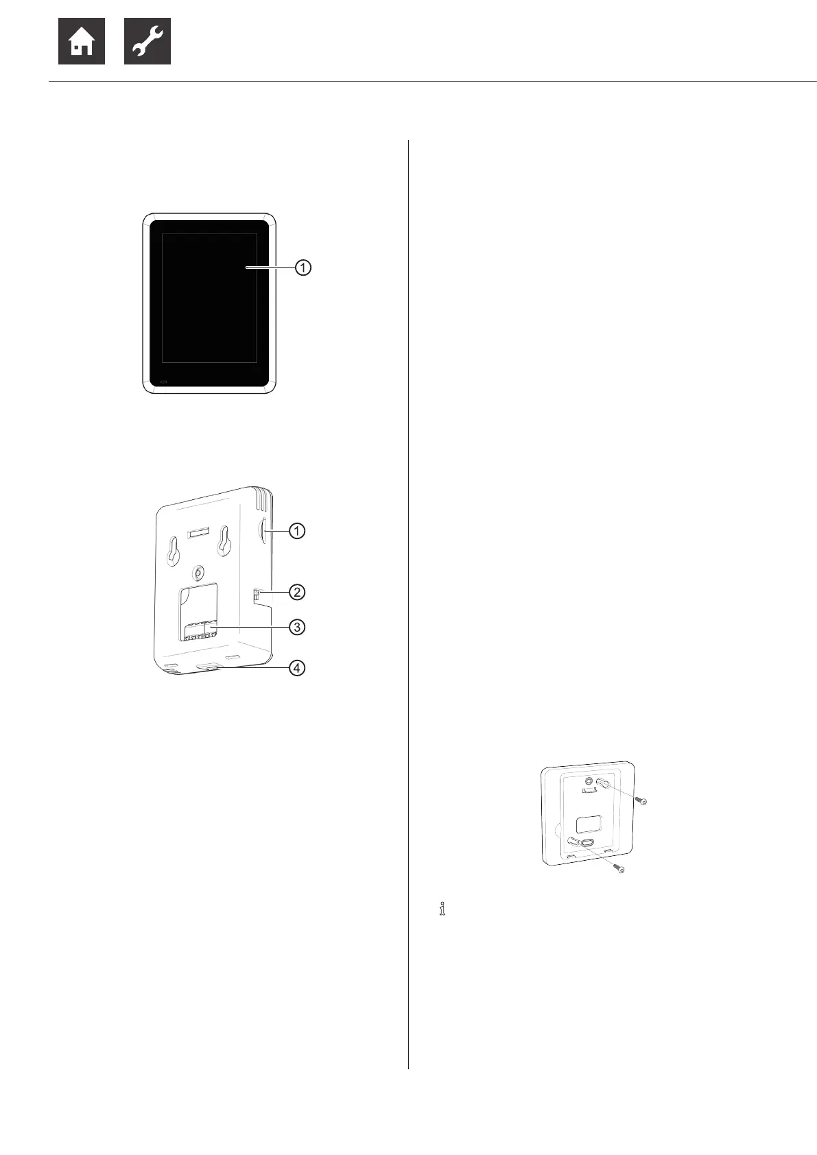
4.1 Unit components
Front view
1 Touch display
Side view and rear view
1 Slot for Micro SD card
“10 Software-Update”, page 20
2 Operating switch for manual on/off
3 Terminal block X1
4 Micro USB connection (for service purposes
only)
5 Installation
Installation inside the building only.
► Dispose of the transport and packaging material
in an environmentally friendly way and in accord-
ance with local regulations.
The temperature and humidity sensors integrated in the
room control unit must not be prevented from measur-
ing a correct room temperature and humidity. Unsuita-
ble installation locations are, for example:
● in a niche
● between shelves
● behind a curtain
● near a heat source
● in a draught area of the external door or a window
● in direct sunlight
Closed radiator thermostats for room tempera-
ture-controlled heating systems can also cause prob-
lems.
► Radiator or underfloor heating valves of the main
room must be kept permanently open for room
temperature controlled systems.
Only one room control unit can be connected for each
heat pump.
Mount the room control unit in the reference room (e.g.
living room) approx. 1.5 m above the floor. Directly on
the wall or using the wall holder supplied.
► To mount the room control unit directly, attach 2
screws that are suitable for the wall material (if
necessary with wall plugs) to the wall at a hori-
zontal distance of 32 mm ( “Dimensonal draw-
ings”, page 23) and 35 mm above the wall out-
let of the connection cable.
► If the supplied wall holder is used, attach 2 screws
that are suitable for the wall material (if necessary
with wall plugs) to the wall at a diagonal distance
of 60 mm ( “Dimensonal drawings”, page 23).
Do not overtighten the screws so that the wall
holder does not become deformed.
NOTE
The wall holder can also be screwed to a cav-
ity or flush-mounted socket (screw distance
60 mm).