Switch Setting
: CENTER
: OFF
: CENTER
: 1/4" JACK
: INSERT
: ONMASTER MIX
HP MIXING
MIC SW
CROSS FADER ASSIGN
MULTI I/O SEND/RETURN
MULTI I/O MODE
UTILITY settings
When starting diagnosis, perform the factory reset
to return it to the factory default.
: OFF
: OFF
: ON
MASTER ISOLATOR
CH CUE
MASTER CUE
4.1, 4.2
OVERALL WIRING
DIAGRAM
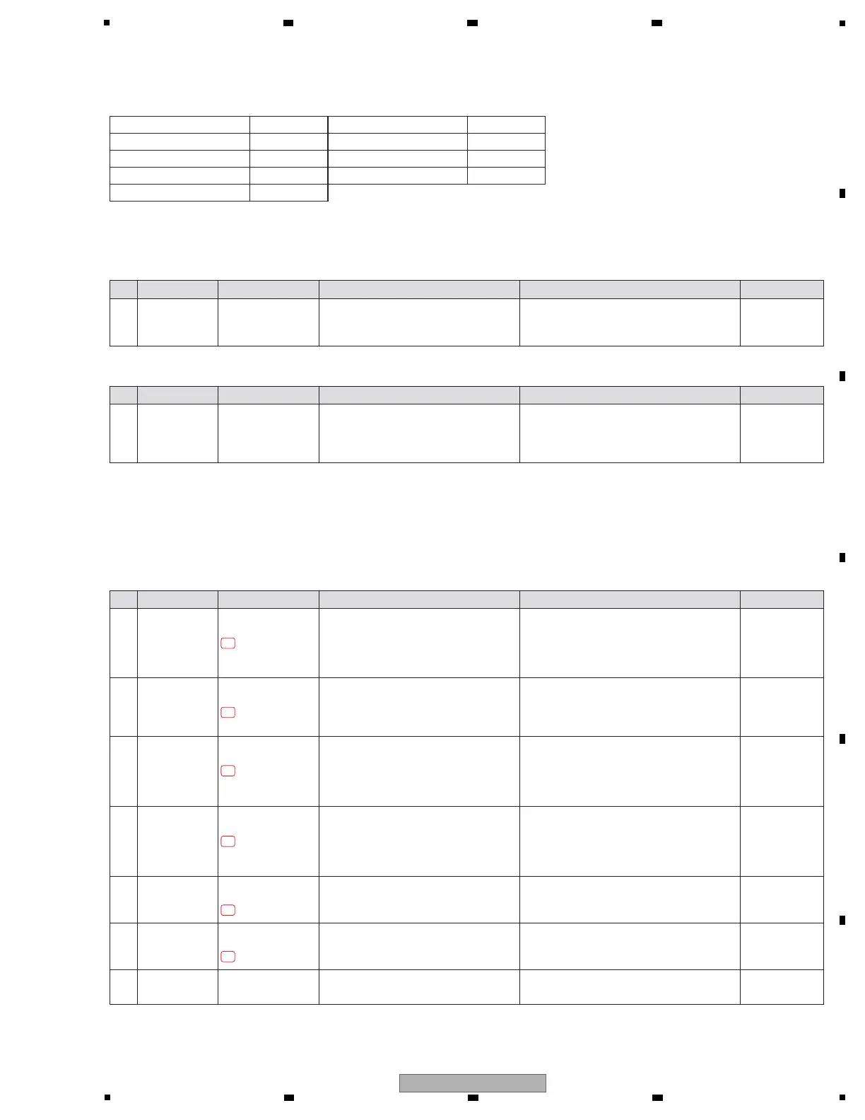
Step Cause Diagnostics Point Item to be Checked Corrective Action Reference
Step Cause Diagnostics Point Item to be Checked Corrective Action Reference
1
Disconnection,
breakage, or
loose connection
of internal wires
Relevant part Check that all the wires are securely
connected.
Check that there is no breakage in the
wires.
Securely connect the wires. If a wire is broken,
replace it.
4.5
POWER BLOCK
DIAGRAM
5.4
INFORMATION
ON POWER
DIAGNOSTICS
1
Defect in the power
source corresponding
to the
defective location
Power to the IC, etc.
that is assumed to be
defective
Check if there is a problem in power
supplied to the location to be diagnosed.
If there is any problem, check the power source,
referring to the "POWER BLOCK DIAGRAM"
then repair.
[0] Prior Confirmation
[0-1] Checking Internal Wires
[0-2] Prior confirmation of power
4.5
POWER BLOCK
DIAGRAM
1
SW power defect,
Wire defect
SW POWER SUPPLY
connector P4 1 pin
Check for the V+12E power. Set SW POWER SUPPLY P4 connector to OPEN.
! If the V+12E power can be confirmed, replace
the wire and go to step 2.
! If not, the SW POWER SUPPLY may be
defective. Replace it.
2 Power defect MAIN Assy
TP V+12E
Check for the V+12E power. ! If the V+12E power can be confirmed, go to
step 3.
! If not, the MAIN Assy may have a short circuit.
Check for the status of soldering and replace it.
4.5
POWER BLOCK
DIAGRAM
5.4
INFORMATION
ON POWER
DIAGNOSTICS
4 Power defect MAIN Assy
TP V+3R3E
Check for the V+3R3E power. ! If the V+3R3E power can be confirmed, go to
step 5.
! If not, IC217 or MAIN Assy may be defective.
Check for short circuit on the MAIN Assy, and
replace IC217 if there is no problem.
4.5
POWER BLOCK
DIAGRAM
5.4
INFORMATION
ON POWER
DIAGNOSTICS
3 Power defect MAIN Assy
TP V+5E
Check for the V+5E power. ! If the V+5E power can be confirmed, go to
step 4.
! If not, IC215 or MAIN Assy may be defective.
Check for short circuit on the MAIN Assy, and
replace IC215 if there is no problem.
5 RESET signal
abnormality
UCOM Assy
TP PNL1_RST_IN
Check for the PNL1_XRST signal. !
If an output signal can be confirmed, go to step 6.
!
If not, RESET IC (IC8407) block may be defective.
Check for the status of soldering and replace it.
6 16 MHz CLK
abnormality
UCOM Assy
X8401 1 or 3 pin
Check for the 16M_CLK (3.3 V 16 MHz)
signal.
!
If an output signal can be confirmed, go to step 7.
!
If not, the crystal (X8401) block may be defective.
Check for the status of soldering and replace it.
7 PNL1 UCOM
defect
UCOM Assy
IC8406
If the symptom persists after the above
corrections.
The PNL1 UCOM
(IC8406)
may be defective.
Check for the status of soldering and replace it.
—
—
—
—
[1] Failure in Startup
[1-1] The unit does not turn on, and the LED of the MIDI START/STOP (WAKE UP) button does not flash
EV power system (V+12E, V+5E, V+3R3E) failure, or PNL1 UCOM (IC8406) startup error may be suspected.
If MIDI START/STOP (WAKE UP) LED flashes, see "5.4 INFORMATION ON POWER DIAGNOSTICS".
1-1
1-2
1-3
1-4
1-5
1-6
Step Cause Diagnostics Point Item to be Checked Corrective Action Reference
 Loading...