Contents
[0] Prior Confirmation
[0-1] Checking Internal Wires
[0-2] Prior confirmation of power
[1] Failure in Startup
[1-1] The unit does not turn on, and the LED of the
MIDI START/STOP (WAKE UP) button does not flash
[2] Error Indications
[2-1] Error Indications on the product GUI
[2-1-1] "E-0001" is displayed
[2-1-2] "E-0002" is displayed
[2-1-3] "E-0004" is displayed
[2-1-4] "E-0008" is displayed
[2-1-5] "E-0010" is displayed
[2-1-6] "E-0020" is displayed
[2-1-7] "E-0040" is displayed
[2-1-8] "E-0080" is displayed
[2-1-9] "E-0100" is displayed
[2-1-10] "E-0200" is displayed
[2-1-11] "E-0400" is displayed
[2-2] Error Indications on the MAIN Assy debug LED and
the product LED
[2-2-1]
The debug LED for USB/ETHER UCOM (D601) repeat
the operation of two flashing and one second off
[2-2-2]
The debug LED for USB/ETHER UCOM (D601) repeat
the operation of five flashing and one second off
[2-2-3]
The debug LED for USB/ETHER UCOM (D601) keep
lighting on
[2-2-4]
The debug LED for MAIN CPU/DSP(DSP) (D1501)
keep lighting on
[2-2-5]
The debug LED for MAIN CPU/DSP(DSP) (D1501)
is flashing at a cycle of about 300 ms
[2-2-6]
The debug LED for MAIN CPU/DSP(ARM) (D1701)
repeat the operation of two flashing and one second off
[2-2-7]
The debug LED for SUB DSP (D1901) keep lighting off
[2-2-8]
MIDI START/STOP (WAKE UP) LED keep
f
lashing at
a cycle of about 3 seconds
[2-2-9]
MIDI ON LED keep flashing at a cycle of about 250 ms
[3] AUDIO INPUT
[3-1] No signal is input to the LINE, PHONO connectors
[3-2] No signal is input to the DIGITAL connector
[3-3] No signal is input to the MIC1/MIC2 connectors
[3-4] No signal is input to the
RETURN (EXT1, EXT2)
connectors
[3-5] No signal is input to the RETURN
(
MULTI I/O
)
connector
[4] AUDIO OUTPUT
[4-1] No signal is output from the
MASTER1/MASTER2/BOOTH
[4-2]
No signal is output from the REC/SEND (EXT1, EXT2, MULTI I/O)
[4-3]
No signal is output from the PHONES (PHONES A/PHONES B)
[4-4] No signal is output from the DIGITAL MASTER OUT
[5] LCD
[5-1] Nothing is displayed on the LCD (LEDs keep lighting on)
[6] Touch panel
[6-1] No work of the Touch panel
[7] LAN
[7-1] No LAN communication.
[8] Crossfader
[8-1] Abnormal function of the crossfader
[8-2] No work of the crossfader
[9] USBA/USBB
[9-1] USBA/USBB does not recognize the unit
[10] MULTI I/O
[10-1] A connected device does not recognize the unit
[11] DIN MIDI
[11-1] MIDI device does not recognize the unit
[12] Firmware update
[12-1] Firmware cannot be updated
* Point to be checked – Assys are classified with prefix.
[1-**] MAIN Assy, UCOM Assy
[2-**] MAIN Assy, AIN Assy, UCOM Assy
[3-**] AIN Assy, MAIN Assy
[4-**] MAIN Assy, AOUT Assy, HPPW Assy
[5-**] LCDB Assy, UCOM Assy, MAIN Assy
[6-**] LCDB Assy, UCOM Assy
[7-**] MAIN Assy
[8-**] CRFB Assy, UCOM Assy, BFXB Assy
[9-**] MAIN Assy, USBB Assy
[10-**] MAIN Assy, USBA Assy, USBP Assy
[11-**] MAIN Assy
[12-**] UCOM Assy
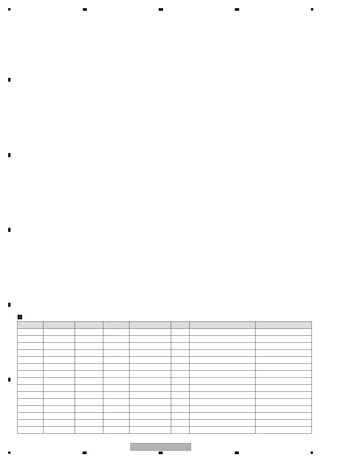
IN or OUT Measure CH
IN CH IN LEVEL IN FREQUENCY RL Other Settings Other Settings
IN LINE
CH1/2/3/4/5/6
0 dBV 1 kHz — CH TRIM VR Max —
IN PHONO CH1/3/4/6 -40 dBV 1 kHz — CH TRIM VR Max —
IN DIGITAL
CH1/2/3/4/5/6
0 dBFS 1 kHz — CH TRIM VR Center —
IN MIC MIC1/2 -40 dBV 1 kHz — MIC LEVEL VR Max All EQs Center
IN RETURN EXT1/EXT2 0 dBV 1 kHz — MASTER MIX LEVEL VR Max —
IN RETURN MULTI I/O 0 dBV 1 kHz — MULTI I/O LEVEL VR Max —
IN USB
USB1/2/3/4/5/6
0 dBFS 1 kHz — CH TRIM VR Center —
—
CH SEND VR Max
—
IN LAN LINK — — — Connect with CDJ-2000NXS2 —
OUT
MASTER1/2
CH1/LINE 0 dBV 1 kHz 10 kΩ MASTER LEVEL VR Center All EQs Center / FADER Max
OUT BOOTH CH1/LINE 0 dBV 1 kHz 10 kΩ BOOTH LEVEL VR Center All EQs Center / FADER Max
OUT REC CH1/LINE 0 dBV 1 kHz 10 kΩ All EQs Center / FADER Max
OUT
SEND (EXT1/EXT2)
CH1/LINE 0 dBV 1 kHz 10 kΩ All EQs Center / FADER Max
MULTI I/O LEVEL VR MaxOUT
SEND (MULTI I/O)
CH1/LINE 0 dBV 1 kHz 10 kΩ All EQs Center / FADER Max
OUT PHONES A/B CH1/LINE 0 dBV 1 kHz 32 Ω PHONES LEVEL VR Center All EQs Center / FADER Max
OUT DIGITAL OUT CH1/LINE 0 dBV 1 kHz 110 Ω All EQs Center / FADER Max
Measure the output diagnosis at the CH1 LINE input.
Measurement Condition