Do you have a question about the Alpine LC70-69P and is the answer not in the manual?
Important warnings and cautions regarding connections, wiring, and installation safety.
Steps like disconnecting the battery and ensuring correct wiring connections.
Lists required tools such as trim tools, sockets, screwdrivers, and drill bits.
Lists tools like Rivnut Tool, Electric Drill, Multimeter, Marker, Hammer, and cutting tools.
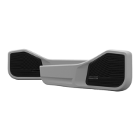
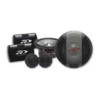
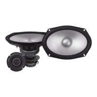
Lists front/rear exocasing, tough grills, tweeter housings, and chrome rings.
Lists LED puddle lights.
Lists USB cables, voltage regulator, and associated brackets/screws.
Lists rivnuts, bolts, screws, templates, sandpaper, zip ties, and tape.
Begin by removing all door cards from the front doors.
Pry up the front edge of the electric window panel to detach it from the armrest.
Remove covers from the grab handle to access and remove screws safely.
Unscrew the visible screws, including the final one holding the door handle.
Slide the door handle mechanism forward and away to detach it.
Use a trim tool to pry and release the plastic push clips around the door panel perimeter.
Carefully maneuver the door card to pull the handle through and feed the wiring harness.
The tear-down process now proceeds to the rear door cards.
Use a trim removal tool to lift the window control panel from the armrest.
Push down the locking tab on the harness plug and pull it from the control panel.
Pry loose screw covers and remove arm rest and door handle screws using a Phillips screwdriver.
Slide the handle forward and out to free it from the door after screw removal.
Use a trim tool to pry and release each plastic push clip around the rear door panel.
Maneuver the rear door card to pull the handle through and feed the wiring harness.
Use a trim removal tool to carefully pry under the dash panel to begin removal.
Apply firm pressure, levering from the front, to release the panel's multiple clipping points.
Remove the hex bolt below the panel with an 8mm spanner and replace it with the supplied screw.
Remove the factory speaker cover, then use a 10mm socket to remove speaker bolts and a screwdriver to release the plug.
Turn over front door cards, remove bottom plastic clips, and place template on the rear, aligning with clip holes.
Secure the template with masking tape and mark pre-cut holes for precision drilling.
Pre-drill door cards with 3mm and 6mm bits, then draw an oval for speaker clearance.
Remove the template and drill three back holes with a 9mm bit for the map pocket, drilling slowly.
Cut the speaker hole using a jigsaw, cutting outside the line for proper clearance.
Soft test mount the door pod by aligning pre-drilled holes, using some screws temporarily.
Place the plastic push clips back onto the door card.
Test mount the assembly to the door by aligning push clips with mounting holes.
Draw ovals on the sheet metal for clearance and mark rivnut locations using boss holes.
After marking, remove the door card and disassemble it.
Use sheet metal cutting tools, like an air hacksaw, to cut the marked speaker clearance hole.
Mark holes for rivnuts with a punch, then drill pilot holes (3mm) and rivnut holes (9mm).
Clean sharp edges with sandpaper and rust-proof exposed bare metal.
Use a Rivnut tool to mount M6 Rivnuts into the 9mm holes in the door sheet metal.
Turn over rear door cards, remove bottom clips, and place template on the rear, aligning with clip holes.
Secure the rear door template with masking tape, noting its reusability.
Mark sheet metal for cutting clearance and cut the speaker hole using a jigsaw.
Mark holes for rivnuts with a punch, then drill pilot holes (3mm) and rivnut holes (9mm).
Perform soft test mounts of the door pod on the door, aligning holes and using screws.
Place the plastic push clips back onto the rear door card.
Mark sheet metal for cutting clearance using the exocasing's speaker cut-out.
Mark sheet metal for cutting clearance and cut the speaker hole using an air hacksaw.
Mark holes for rivnuts with a punch, then drill pilot holes and rivnut holes.
After marking, remove the rear door card and disassemble it.
Drill holes for rivnuts, clean edges, and mount M6 Rivnuts using a Rivnut tool.
Mount USBs in the exocasing, routing cables loosely near the mounting area.
Mount USB port nut and clip LED into the exocasing, noting R/L markings.
Route wires through exocasing channels, secure them, and tie down cables.
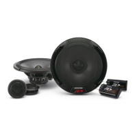
Place the component speaker into the exocasing pod, using the bosses for alignment.
Secure speaker with screws, then insert rubber plugs into drilled holes.
Secure the exocasing to the door card using the supplied mounting screws.
Mount USBs in the exocasing, routing cables loosely near the mounting area.
Mount USB port nut, secure wires with zip tie, and feed excess wiring out.
Place the rear exocasing over the door pod and secure it to the card with mounting screws.
Start assembling tweeter panels by taking an Alpine Tweeter and twisting the back panel.
Feed wires, install tweeter into panel, and lock with a chrome ring.
Mount voltage regulator to bracket and install in factory speaker location or passenger side.
Ensure wire length for convergence, connect LED positive to constant power and ground.
Connect regulator power/ground and route wiring harnesses from doors into the vehicle.
Terminate wires, mount assembly to door, and ensure clips are reattached.
Secure exocasing with bolts and attach the Tough Grill by inserting and pushing clips.
Reassemble the window control panel and remount the door handle to complete front exocasing installation.
Terminate wires, mount assembly to rear door, and ensure clips are reattached.
Secure the mounted door card/assembly with M6 bolts using a 10mm socket and wrench.
Attach the Tough Grill by inserting the back edge into the pod and pushing clips from back to front.
Reassemble the window control panel and remount the door handle.
Feed speaker wire to dash and install tweeter assembly by manoeuvring clips and levering downward.
The Alpine Tweeter is now mounted into the dash.
Test and validate system for proper functionality and fitment, including power, sound, and lights.
Congratulations, the installation is now complete.
| Sensitivity | 88dB |
|---|---|
| Impedance | 4 Ohms |
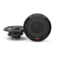
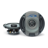
| Tweeter Composition | Silk Dome |
| Frequency Response | 65Hz - 22kHz |
| Speaker Size | 6.75 inches |