4–2 Chapter 4: Development Board Setup
Factory Default Switch and Jumper Settings
Cyclone V SoC Development Kit May 2013 Altera Corporation
User Guide
Factory Default Switch and Jumper Settings
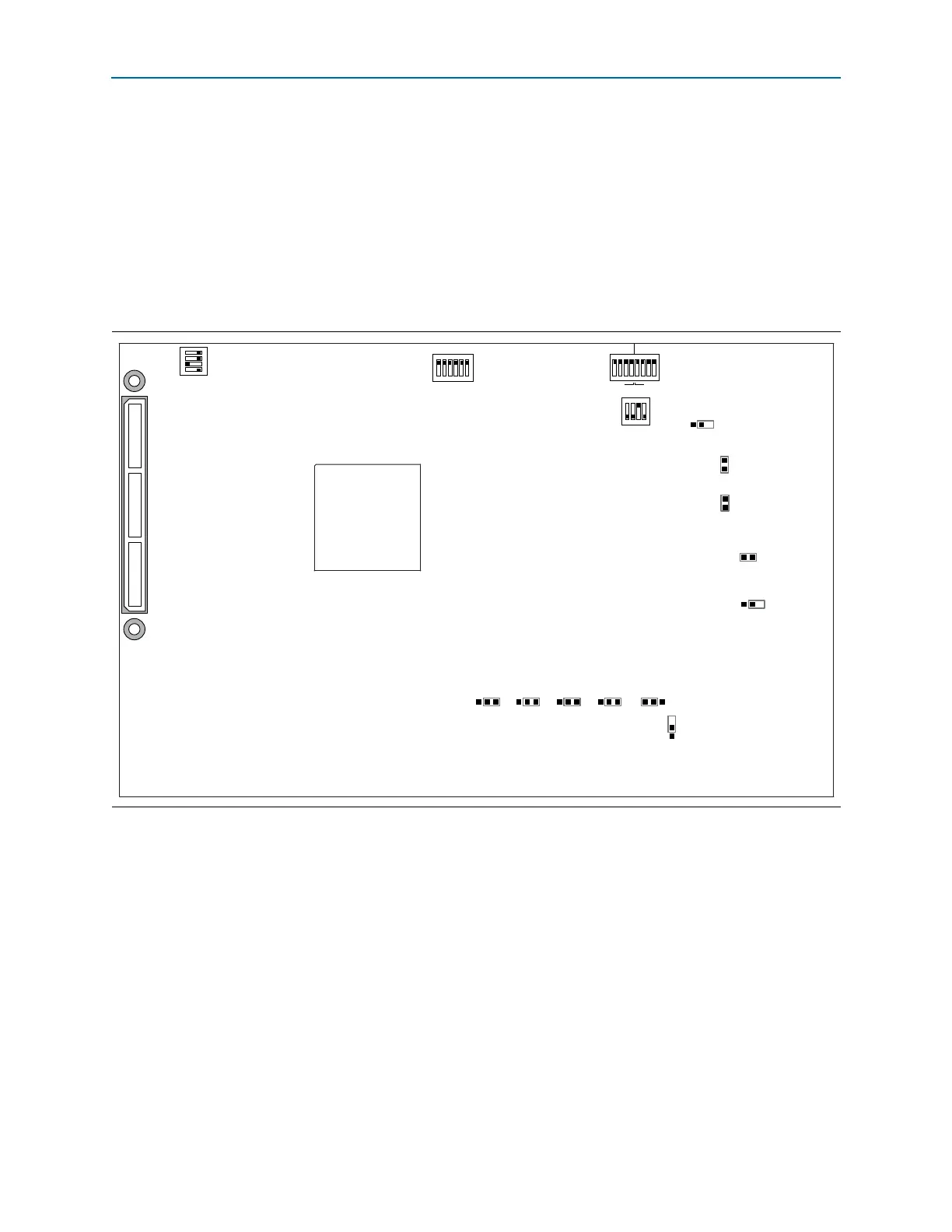
This section shows the factory settings (Figure 4–1) for the Cyclone V SoC
development board. These settings ensure that the Board Update Portal and Golden
System Reference design function properly.
1 The SD card, Max V system controller, and CFI flash are already programmed with
the factory default files. For more information, refer to Appendix A, Programming
Flash Memory.
Figure 4–1. Switch Locations and Default Settings
J5
9V
J13
OSC1_CLK_SEL
J16
J31
I2C
SPI
J26 J27 J28 J29 J30
JTAG_MIC_SEL
J6
JTAG
HPS SEL
J7
JTAG
SEL
SW2
SW3
1 2 3 4
SECURITY
FACT LOAD
Si570
CLK125A
01234
MSEL
CLKSEL0 CLKSEL1 BOOTSEL0 BOOTSEL1 BOOTSEL2
HPS
FPGA
HSMC
MAX
ON
ON
1 2 3 4 5 6
SW4
JTAG ENABLE
1 2 3 4
ON
SW1
3 2 1 0 3 2 1 0
HPSFPGA
ON
1 2 3 4 5 6 7 8