6–16 Chapter 6: Board Test System
The Clock Control
Cyclone V SoC Development Kit May 2013 Altera Corporation
User Guide
f For more information about the Si570/Si571 and the Cyclone V development board’s
clocking circuitry and clock input pins, refer to the Cyclone V SoC Development Board
Reference Manual.
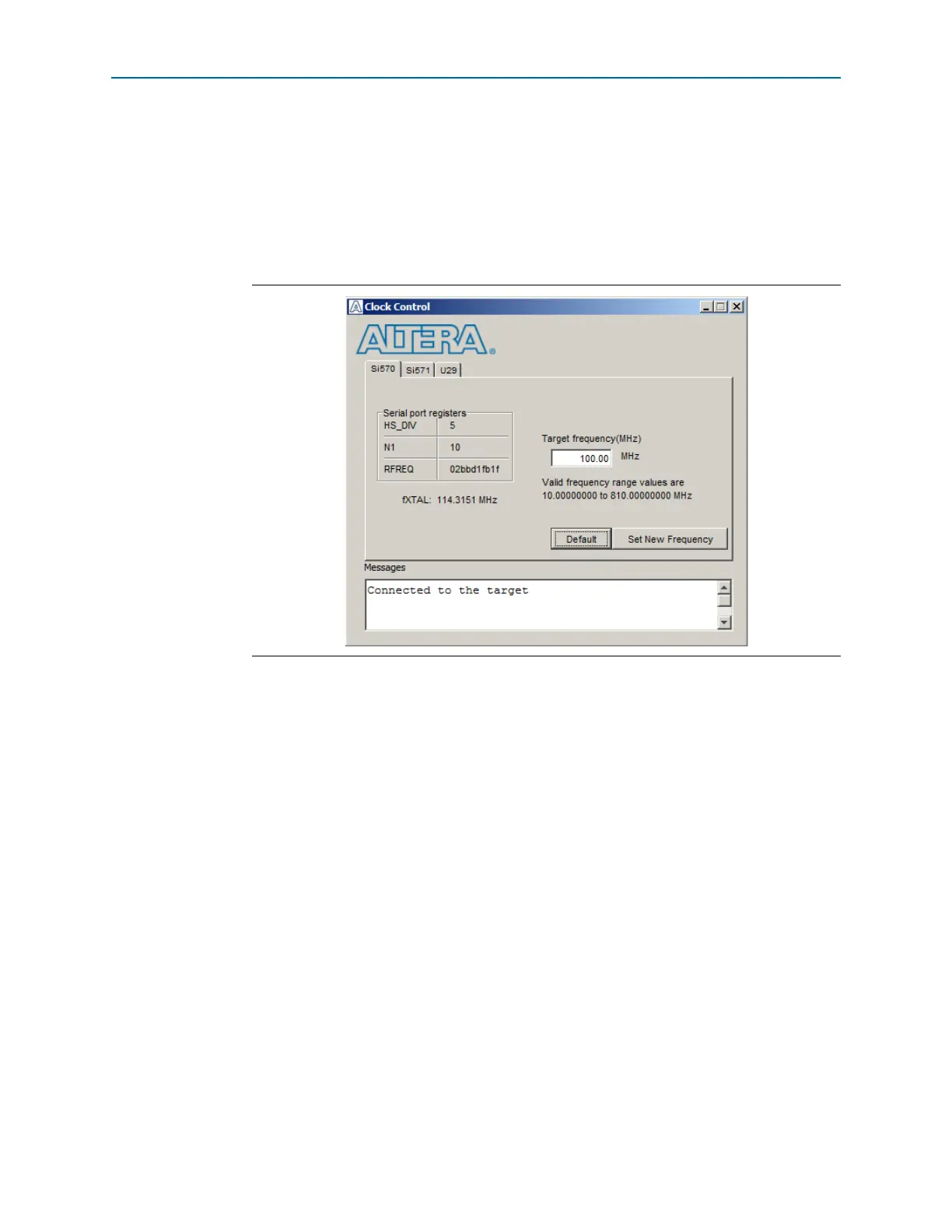
The Clock Control communicates with the MAX V device on the board through the
JTAG bus. The Si570 and Si571 programmable oscillators are connected to the MAX V
device through a 2-wire serial bus. Figure 6–8 shows the Clock Control Si570 tab.
The following sections describe the Clock Control controls.
Serial Port Registers
The Serial port registers control shows the current values from the Si570 registers.
f For more information about the Si570 registers, refer to the Si570/Si571 data sheet
available on the Silicon Labs website (www.silabs.com).
fXTAL
The fXTAL control shows the calculated internal fixed-frequency crystal, based on the
serial port register values.
For more information about the f
XTAL
value and how it is calculated, refer to the
Si570/Si571 data sheet available on the Silicon Labs website (www.silabs.com).
Target Frequency
The Target frequency control allows you to specify the frequency of the clock. Legal
values are between 10 and 810 MHz with eight digits of precision to the right of the
decimal point. For example, 421.31259873 is possible within 100 parts per million
(ppm). The Target frequency control works in conjunction with the Set New
Frequency control.
Figure 6–8. The Clock Control