6–4 Chapter 6: Board Test System
Using the Board Test System
Cyclone V SoC Development Kit May 2013 Altera Corporation
User Guide
1 If you plug in an external USB-Blaster cable to the JTAG header (J23), the On-Board
USB-Blaster II is disabled.
1 JTAG DIP switch bank (SW4) selects which interfaces are in the chain. Refer to
Table 4–3 on page 4–4 for detailed settings.
f For details on the JTAG chain, refer to the Cyclone V SoC Development Board Reference
Manual. For USB-Blaster II configuration details, refer to the On-Board USB-Blaster II
page.
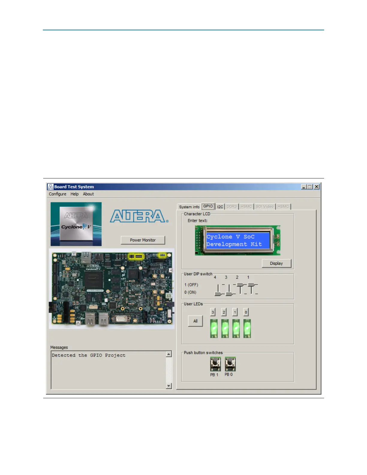
The GPIO Tab
The GPIO tab allows you to interact with all the general purpose user I/O
components on your board. You can write to the character LCD, read DIP switch
settings, turn LEDs on or off, and detect push button presses. Figure 6–2 shows the
GPIO tab.
The following sections describe the controls on the GPIO tab.
Figure 6–2. The GPIO Tab