84
•
MN-35949
•
Rev 07
•
01/20
•
Combitherm® CT PROformance™ and CT Classic™ Series Technical Service Manual
Troubleshooting
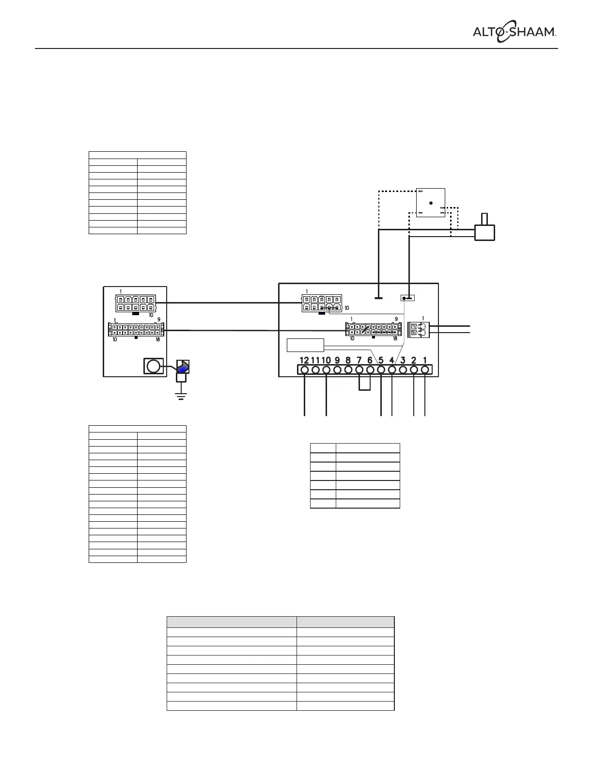
CONVERSION BOARD
BURNER
IGNITION MODULE
RESET
L HD AL N
+
FS
GND
N J6J2
HOT
SURFACE
IGNITOR
J5
J1
J3
J4
18_PIN
10_PIN
FLAME
ROD
HSI
CONTROLLER
208-240V
380-415V
J3
10_PIN
CONNECTION DIAGRAM
FROM
TO
1 J3-1
2 J3-2
3 J3-3
4 J3-4
5 J3-5
6 J3-6
7 J3-7
8 J3-8
9 J3-9
10 J3-10
High Voltage Heat Demand
Alarm output – Phase
HSI output – Phase
Not used
Main Power Line – Phase
Not used
Alarm output – Neutral
HSI output – Neutral
Neutral
Main Power Line – Neutral
18_PIN
CONNECTION DIAGRAM
FROM
TO
1 J5-1
2 J5-2
3 J5-3
4 J5-4
5 J5-5
6 J5-6
7 J5-7
8 J5-8
9 J5-9
10 J5-10
11 J5-11
12 J5-12
13 J5-13
14 J5-14
15 J5-15
16 J5-16
17 J5-17
18 J5-18
External Reset switch input
NC
Flame on (open collector)
High Limit switch input – HL
NC
NC
NC
NC
NC
NC
Supply (24V)
High Limit switch – supply (24V)
Supply (6V)
GND
GND – External Reset switch
GND
GND
GND
INPUT
HSI
OUTPUT
Timings Value
Waiting time 0 s (adjustable)
Glowing time 21 s (see NOTE)
5 s
Safety time
2 Number of ignition trials
1 s Flame failure response time
0 s Stabilization time
- Post purge time
- Pump over run time
-
Anti cycling time
NOTE: Duration of Glowing = Glowing time + minimal 4 s in Safety time
PROformance and Classic Gas ovens with a conversion board along with a 10 Pin
and an 18 Pin connector on the burner ignition module
L
Line
HD Heat demand
Alarm
AL
Neutral N
Ground GND
Flame sense FS
Hot surface ignitor HSI
1
1
10
10
9
1
18
1
10
10
9
18
1
K1Alarm
 Loading...