SYSTEM OPERATION
21
The heating portion of the refrigeration cycle is similar
to the cooling cycle. By energizing the reversing valve
solenoid coil, the ow of the refrigerant is reversed. The
indoor coil now becomes the condenser coil, and the
outdoor coil becomes the evaporator coil.
The check valve at the indoor coil will open by the ow
of refrigerant letting the now condensed liquid refrigerant
bypass the indoor expansion device. The check valve at
the outdoor coil will be forced closed by the refrigerant ow,
thereby utilizing the outdoor expansion device.
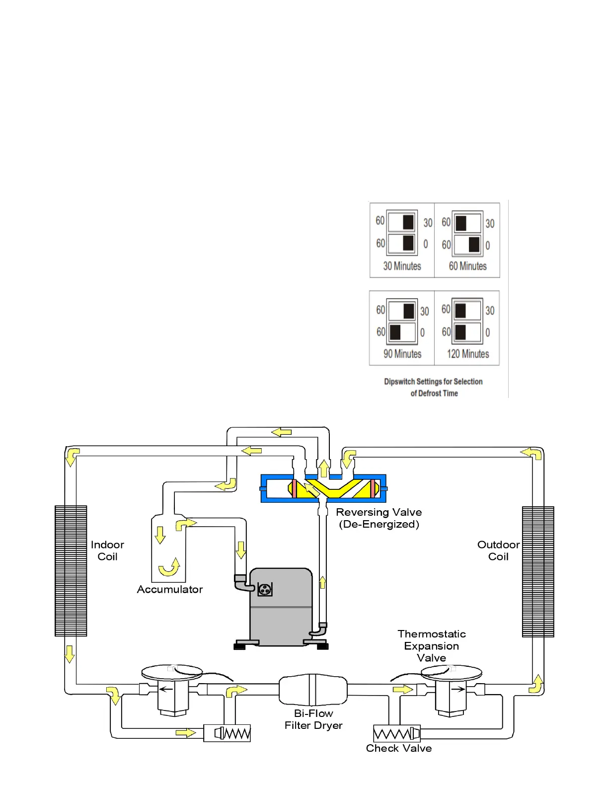
The defrosting of the outdoor coil is jointly controlled by the
UC PCB and the outdoor coil temperature (OCT) sensor.
The OCT sensor is clamped to a feeder tube entering the
outdoor coil. Defrost timing periods of 30, 60, 90 or 120
minutes may be selected via the dipswitch settings on
the UC PCB. During operation, if the coil temperature is
low enough (approximately 31° F), the microprocessor
will accumulate the compressor run time. When the total
compressor run time reaches 30, 60, 90 or 120 minutes,
and there is a call for heat, the PCB will initiate a defrost
cycle.
When the microprocessor detects the coil temperature to
be high enough (approximately 75 0F), or 10 minutes of
maximum defrost cycle time has elapsed, whichever occurs
rst, the defrost cycle is terminated and the timing period is
reset. The eld service personnel can also advance a heat
pump to the defrost cycle by simultaneously pressing the
“TEST” button and the “RECALL” button on the UC board.
Use the dipswitches to select defrost time interval (30, 60,
90 or 120 minutes) See chart below

 Loading...