SERVICING
35
1. Connect refrigerant gages to unit.
2. Disconnect power to outdoor unit.
3. Remove control panel cover.
4. Disconnect black wire from condenser fan motor (single
stage units) or remove plug from control board on 2
stage units. Note: Tape or isolate black wire to prevent
possible short.
5. Apply power to unit and set thermostat to cool and set
for all for cool.
6. Low pressure switch should open at 21 PSIG and auto
reset (close) at approximately 50 PSIG
7. If low pressure switch does not operate in these
parameters replace switch.
The HPC and LPC are wired in series so output at both
switches should be the same when switches are closed
voltage reading should be 6.5vdc or 8.0vac. NOTE: the
Discharge Thermostat is wired in series with the HPC if
DT is open you will read input voltage on the HPC and no
voltage on the output of HPC or LPC.
A run capacitor is wired across the auxiliary and main
windings of a single phase permanent split capacitor
motor. The capacitors primary function is to reduce the line
current while greatly improving the torque characteristics
of a motor. This is accomplished by using the 90° phase
relationship between the capacitor current and voltage
in conjunction with the motor windings, so that the motor
will give two phase operation when connected to a single
phase circuit. The capacitor also reduces the line current
to the motor by improving the power factor.
The line side of this capacitor is marked with “COM” and is
wired to the line side of the circuit.
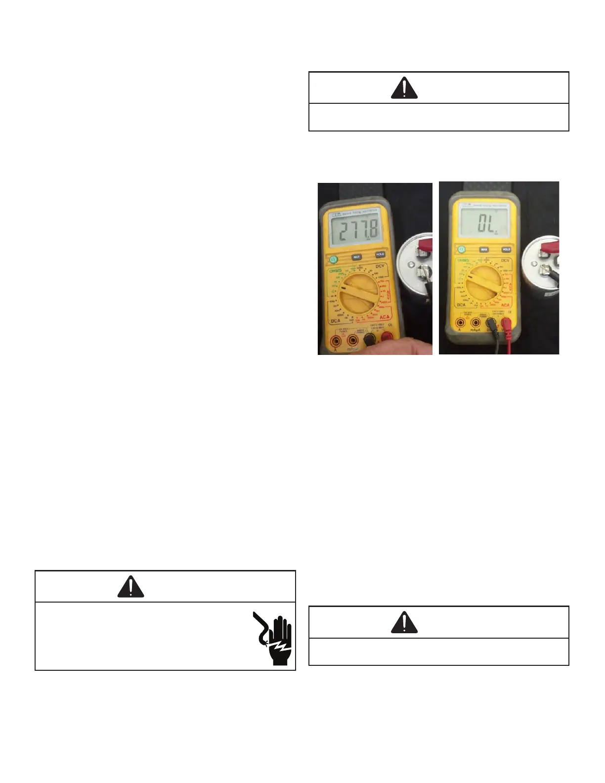
1. Set the meter on Ohm range (Set it at lease 1000
Ohm=1k).
2. Connect the Meter leads to the Capacitor terminals.
3. Digital meter will show a reading momentarily
(Figure 1). Note the reading.
4. Reading will immediately return to the OL = (Open Line)
(Figure 2). Every attempt of Step 2 will show the same
result as was in step 4 and Step 5. This indicates that
the capacitor is good.
5. If there is no Change, then capacitor is dead and must
be replaced.
A. Good Condition - indicator swings to zero and slowly
returns to innity. (Start capacitor with bleed resistor
will not return to innity. It will still read the resistance
of the resistor).
B. Shorted - indicator swings to zero and stops there -
replace.
C. Open - no reading - replace. (Start capacitor would
read resistor resistance.)
1. Remove the capacitor from the circuit.
2. Now Select “Capacitance” on your multi-meter.

 Loading...