SERVICING
37
6. Turn on power to air handler or modular blower.
7. Depress the orange power button on the diagnostic tool
to send a run signal to the motor. Allow up to 5 seconds
for the motor to start.
8. The green LED on the diagnostic tool will blink
indicating communications between the tool and motor.
See table below for indications of tool indicators and
motor actions. Replace or repair as needed.
Confirm 24VAC to
UltraCheck-EZ
TM
tool.
If 24VAC is confirmed,
diagnostic tool is
inoperable.
Motor and control/end
bell are functioning
properly.
Replace motor
control/end bell.
Check motor (see
Motor Check s below).
Replace motor
control/end bell; verify
motor (see Motor
Check s below).
9. Depress the orange power button to turn o motor.
10. Disconnect power. Disconnect diagnostic tool.
11. Reconnect the 4-wire harness from control board to
motor.
Electrical Checks - High Voltage Power Circuits
1. Disconnect power to air handler or modular blower.
2. Disconnect the 5-circuit power connector to the ECM
motor.
3. Turn on power to air handler or modular.
4. Measure voltage between pins 4 and 5 on the 5-circuit
connector. Measured voltage should be the same as
the supply voltage to the air handler or modular.
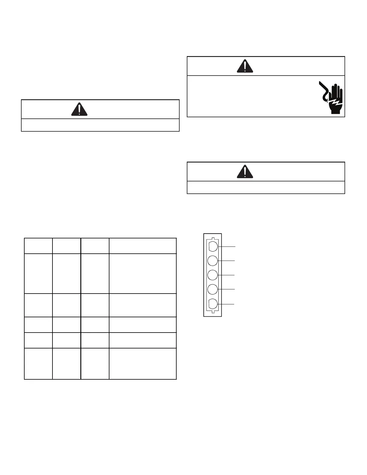
1
2
3
4
5
Lines 1 and 2 will be connected
for 12OVAC Power Connector
applications only
Gnd
AC Line Connection
AC Line Connection
}
5. Measure voltage between pins 4 and 3. Voltage should
be approximately half of the voltage measured in step 4.
6. Measure voltage between pins 5 and 3. Voltage should
be approximately half of the voltage measured in step 4.
7. If no voltage is present, check supply voltage to air
handler or modular blower.
8. Disconnect power to air handler or modular blower.
Reconnect the 5-circuit power harness disconnected in
step 2.

 Loading...