AMETEK Brookeld Page 27 Manual No. M08-372-F1116
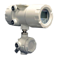
ThefollowingsequenceofdisplayscreenssummarizestheTargetHoldsetupprocedure:
TEST:TRGT HLD: 210.0 s
TRIGGER: 10.0 g
TRGT LOAD: 500 g
SPEED: 0.5 mm/s
* ATTACH PROBE *
PRESS START
TO CONTINUE
* ADJUST POSITION
USING SCROLL SELECT
* PRESS START
DISTANCE 123.5 mm
AUTOZEROING
TEST:TRGT HLD: 210.0 s
TRIGGER: 0.098 N
TRGT LOAD: 4.9 N
SPEED: 0.5 mm/s
Figure III.29
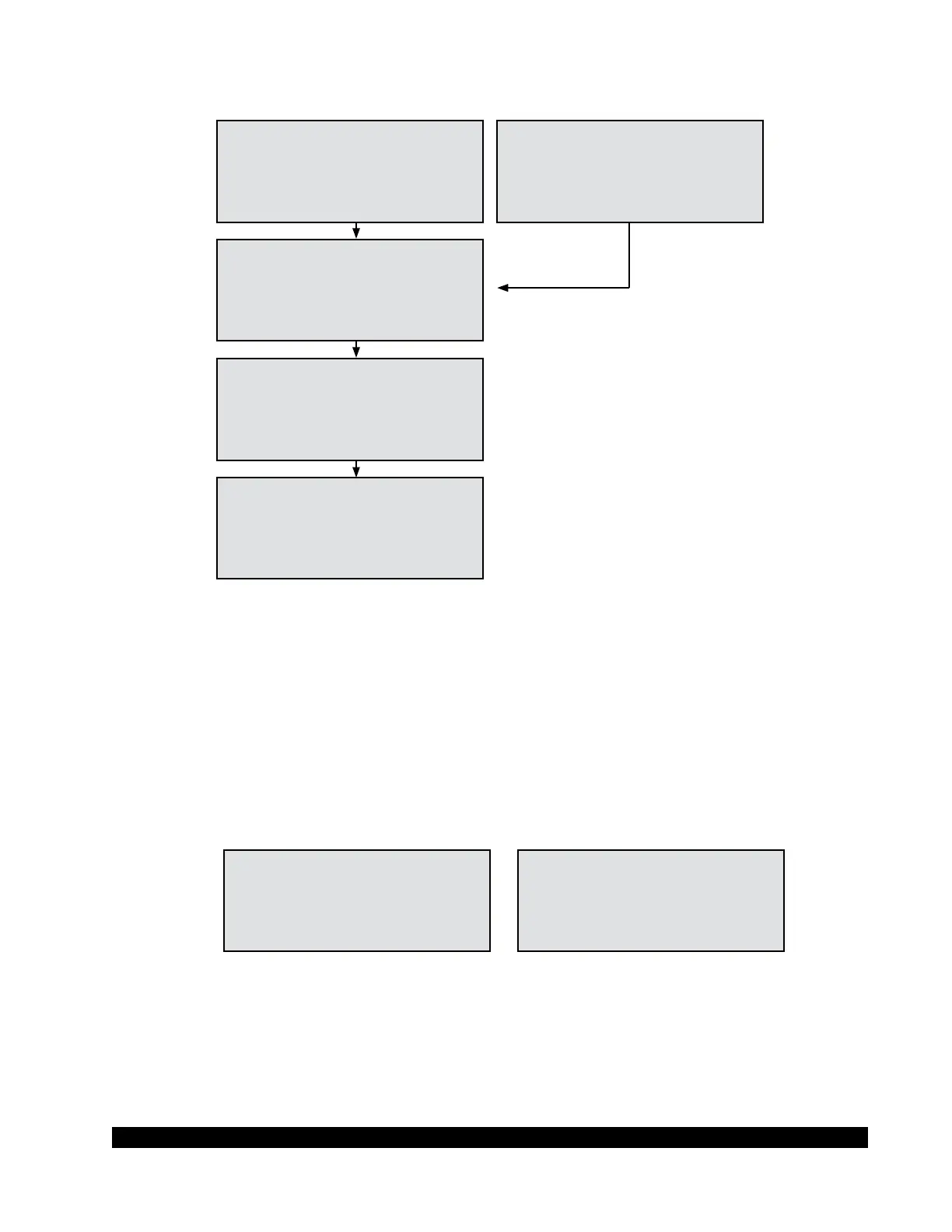
TheCT3displaysthefollowinginformationwhiletheTargetHoldtestisbeingrun.:TIMEAT
TARGET, DEFORMATION, and the current measured LOAD. The sequence of events, and the
correspondingdisplayelds,isasfollows.
The display begins with the TIME at 0 while the probe descends at the selected PRE-SPEED (assigned
by the user in the GLOBAL PARAMETERS screen described elsewhere). Pressing and holding
the START button prior to reaching the TRIGGER load will override the PRE-SPEED setting for
theprobewithadefaultspeedof4.5mm/sec(knownasjogging).TheDISTANCEremainsat0.0
until the TRIGGER load value is reached when the probe makes contact with the sample. The
LOADeldthenstartstodisplaytheactualforcemeasuredbytheCT3.
TEST: TRGT HLD
TIME: 210 s
DISTANCE: 0.0 mm
LOAD: 0.0 g
TEST: TRGT HLD
TIME: 210 s
DISTANCE: 0.0 mm
LOAD: 0.00 N
Figure III.30
When the measured LOAD reaches the assigned TRIGGER value, the probe speed is changed to
the assigned SPEED from the Target Hold setup screen. As the probe approaches the target load
atthepre-assignedspeed,therewillbeaxeddecelerationalgorithmthatreducesthespeedofthe
probe until it reaches the target load, based on a percentage of the load cell full scale. Therefore,
the pre-assigned probe speed only represents the maximum allowable speed. For example, if the
appliedload,whentheTRIGGERpointisreached,issufcientlyclosetothetargetholdload,then
SETUP
SCREENS
PRE-POSITIONING

 Loading...