AMETEK Brookeld Page 8 Manual No. M08-372-F1116
3) PlacetheCT3TextureAnalyzeronasturdy,levelsurface.Adjustthefourfeettoensure
that the instrument is stable.
4) Remove any additional components from the shipping package. Save the shipping container
and packaging for future use.
5) Install base table using the supplied pair of T-bolts and thumbscrews. Position the base
table so that it is approximately centered under the probe. More accurate alignment may
berequiredforcertainxtures.
6) Make sure that the AC power switch at the rear of the CT3 Texture Analyzer is in the OFF
l
o
on
off
position. Connect the power cord to the socket on the back panel of the instrument
and plug it into the appropriate AC line. Position instrument so that the power
cord can be removed easily.
The AC input voltage and frequency must be within the appropriate range as shown on
the model and serial tag of the instrument (located on the back of the CT3).
The CT3 Texture Analyzer must be earth grounded to ensure against electronic failure!
7) If appropriate, connect communication cable which is supplied with Texture Loader software
to the appropriate port for connection to a computer.
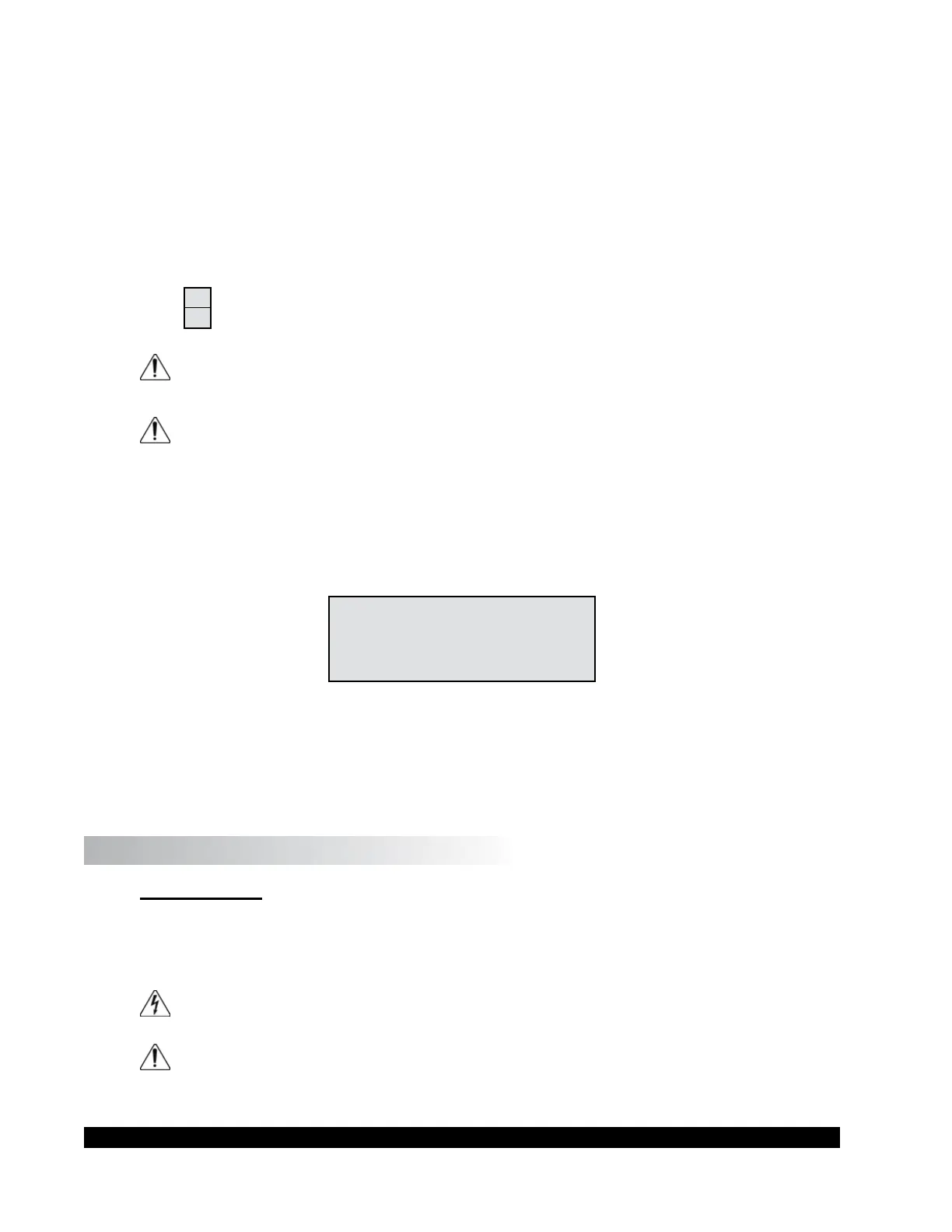
8) TurnthepowerswitchtotheONposition.Thestartupscreenwillindicatethermware
version and load range of the CT3 (Figure I.1).
CT3 VERSION X.X
TEXTURE ANALYZER
XXXX GRAM UNIT
INITIALIZING
Figure I.1
9) Allow the instrument to warm up for 10 minutes.
10) If desired, check calibration according to Section III.9.
I.6 Safety Symbols and Precautions
Safety Symbols
The following explains safety symbols which may be found in this operating manual, or on the
instrument itself.
Indicates hazardous voltages may be present.
Refertothemanualinallcaseswherethissymbolisevident.Usedforspecicwarning
orcautioninformationtoavoidpersonalinjuryordamagetotheinstrument.

 Loading...