User Manual - CTC-1402
10
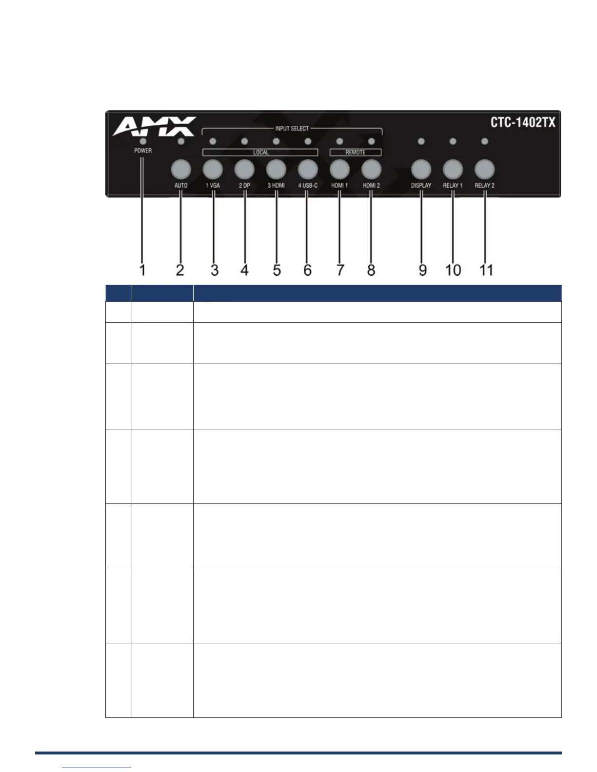
Transmitter Front Panel Description
No. Name Description
1 POWER LED
(Green)
On: The CTC-1402 TX is powered on.
O: The CTC-1402 TX is powered o.
2 Auto Auto Switch Button: Press to enable/disable auto switching function.
LED (Blue): LED is located on the top of the button.
• ON: Input auto switching function is enabled (default).
• O: Input auto switching function is disabled.
3 1 VGA 1 VGA Button: Press to select VGA as input.
LED: LED is located on the top of the button.
• Green: the input has signal and is selected.
• Yellow: the input has signal but is not selected.
• Red: the input has no signal but is selected.
• O: the input has no signal and is not selected.
4 2 DP 2 DP Button: Press to select DP as input.
LED: LED is located on the top of the button.
• Green: the input has signal and is selected.
• Yellow: the input has signal but is not selected.
• Red: the input has no signal but is selected.
• O: the input has no signal and is not selected.
5 3 HDMI 3 HDMI (TX) Button: Press to select the HDMI IN 3 (TX) as input.
LED: LED is located on the left of the button.
• Green: the input has signal and is selected.
• Yellow: the input has signal but is not selected.
• Red: the input has no signal but is selected.
• O: the input has no signal and is not selected.
6 4 USB-C 4 USB-C Button: Press to select USB-C as input.
LED: LED is located on the top of the button.
• Green: the input has signal and is selected.
• Yellow: the input has signal but is not selected.
• Red: the input has no signal but is selected.
• O: the input has no signal and is not selected.
7 HDMI 1 HDMI 1 (RX) Button: Press to select RX HDMI IN 1 as input.
LED: LED is located on the top of the button.
• Green: the input has signal and is selected.
• Yellow: the input has signal but is not selected.
• Red: the input has no signal but is selected.
• O: the input has no signal and is not selected.