UG-1828 Preliminary Technical Data
Rev. PrC | Page 102 of 338
FREQUENCY HOPPING
Before delving into the frequency hopping feature details, the user is recommended to read the Multichip Synchronization section and the
Timing Parameters Control section of this document.
Frequency hopping allows the user to quickly switch radio signals among different frequency channels. For ADRV9001, this is achieved
by retuning the PLL before switching to the frequency channel. There are two local oscillators (LO) inside ADRV9001, therefore we can
ping pong between the two LOs. This means while one LO is being used for on-air signal transmitting for one frequency, the other LO
can be used to prepare for the next frequency. This makes very fast frequency hopping possible. Besides ping pong between two LOs,
ADRV9001 also support single LO for frequency hopping. This allows LO to be retuned while it’s off air. This way the user can separately
hop Rx1/Tx1 and Rx2/Tx2 as well. More of the operation modes will be described in later sections.
This section explains the key parameters of frequency hopping, namely the HOP signal and Tx and Rx Setup signals. They play a key role
in understanding how frequency hopping in ADRV9001 operates and crucial to understand more complicated timing configurations.
Channel use cases and the modes of operation for frequency hopping are also shown. ADRV9001 supports frequency hopping for Tx
only, Rx only and TRx. The propagation delay for the data path must be considered as well, as they will affect the channel use case option.
The proposed modes of operation are based on the allowed time for the PLLs to retune. The number of LOs, number of allowed channels,
and calibration modes are different depending on the different modes of operation.
The concept of frequency hopping table is explained. All frequency parameters will be provided in a frequency hopping table in all modes
of operation. The required parameters of a frequency hopping entry are shown. The different modes of indexing the table are shown as
well.
KEY SIGNALS
The frequency hopping framework involves reconfiguring the analog and digital components to hop to different frequencies.
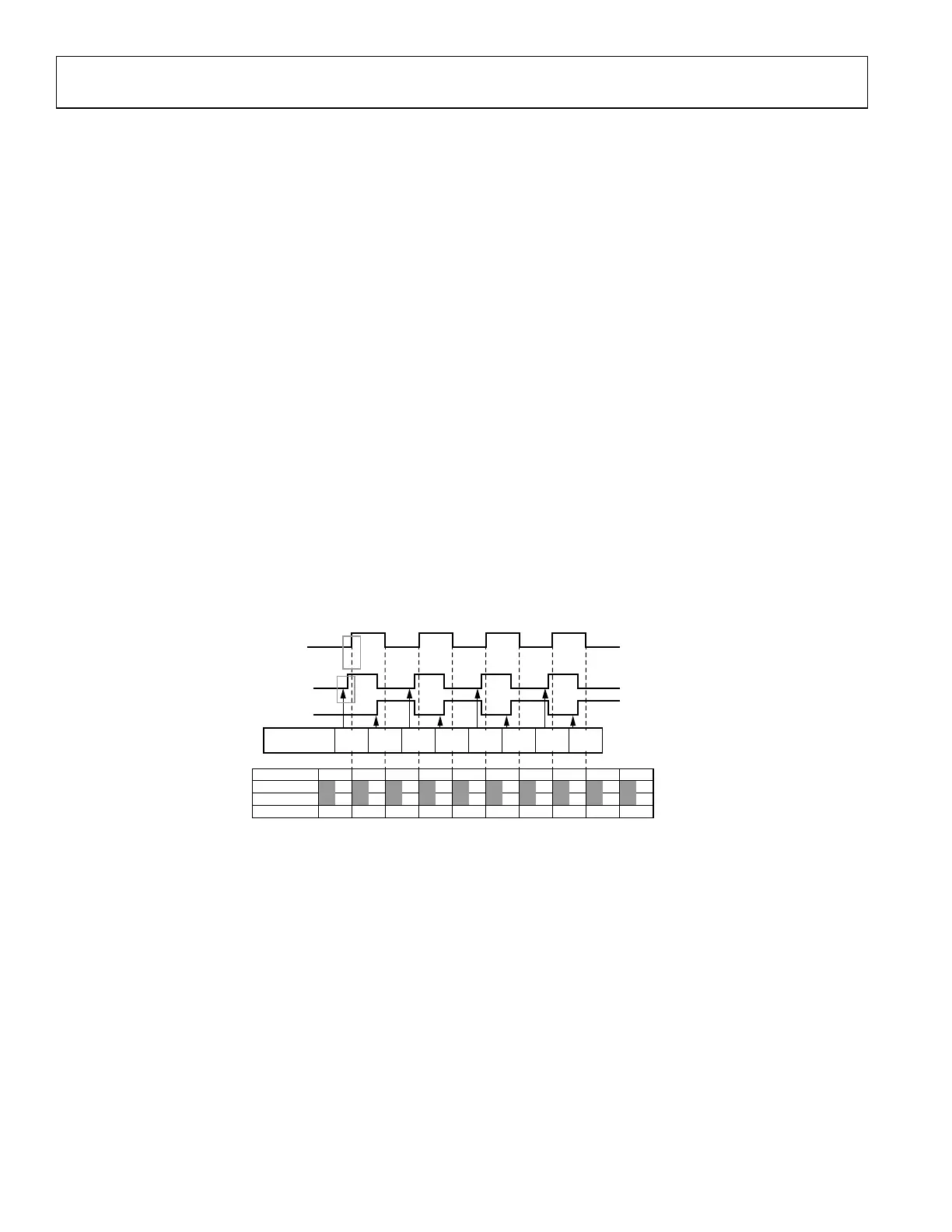
Figure 99 shows a typical frequency hopping timing diagram. In this diagram, we have the HOP signal and the Tx and Rx setup signals,
frequency select, and the frames on the air. Tx and Rx setup signals are Tx and Rx ENABLE hardware signals. In the context of frequency
hopping, they are repurposed as Tx and Rx setup signals. More information on this is shown in the later sections
Figure 99. Typical Timing Diagram for Frequency Hopping
FRAME NO 7
CHANNEL
FREQUENCY
TX
F4
LO LO2
6
RX
F3
LO1
5
TX
F2
LO2
4
RX
F1
LO1
3
TX
F4
LO2
2
RX
F3
LO1
1
TX
F2
LO2
0
RX
F1
LO1
–
–
–
–
–
–
FREQUENCY
SELECT (MSG)
HOP
0 6 754321
Tx SETUP
Rx SETUP
BBIC
BBIC
BBIC
BBIC
24159-083
F1
LO1
F4
LO2
F3
LO1
F2
LO2
F1
LO1
F4
LO2
F3
LO1
F2
LO2
 Loading...