UG-1828 Preliminary Technical Data
Rev. PrC | Page 212 of 338
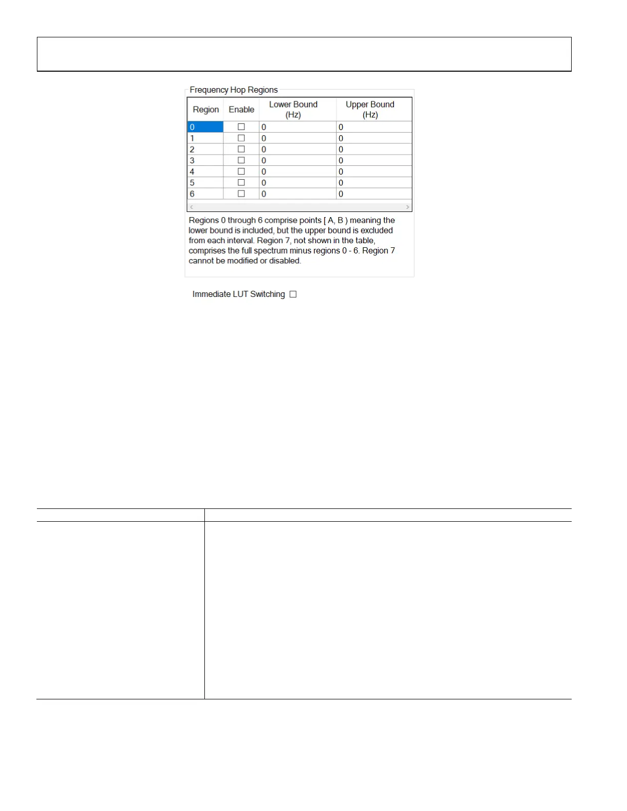
Figure 197. Define Frequency Hop Regions Through TES
Note in this case, immediate LUT switching should be disabled since the LUT switch only happens at the beginning of each hopping
frame with the correct LUT for that LO frequency. In addition, the length of each hopping frame should be sufficient to allow capture of a
specified number of samples at the DPD sampling rate plus the additional time it takes for the system to setup the DPD tracking
calibration. If this condition is not satisfied, DPD could not be performed successfully with FH. For example, if the number of samples is
set as 4096, for LTE20, the DPD sampling rate is at 184.32MSPS (more information about the DPD sampling rate will be provided in
future releases), the hopping frame needs to be longer than 4096/184.32=22.22us.
DPD/CLGC API PROGRAMMING
A set of API commands are provided to set and inspect the DPD/CLGC parameters, which is summarized in Table 85. Board
configuration parameters should be set through ADRV9001 initialization structure. Please refer to the doxygen document for more
details.
Table 85. DPD APIs
DPD Rx Function Name Description
adi_adrv9001_dpd_Initial_Configure Configures the pre initial calibration DPD parameters. Called by
adi_adrv9001_Utilities_InitRadio_Load() as part of device initialization.
adi_adrv9001_dpd_Initial_Inspect Inspects the pre initial calibration DPD parameters.
adi_adrv9001_dpd_Configure Configures the post initial calibration DPD parameters.
adi_adrv9001_dpd_Inspect Inspects the post initial calibration DPD parameters.
adi_adrv9001_dpd_coefficients_Set Sets DPD coefficients to be used at the next start of DPD.
adi_adrv9001_dpd_coefficients_Get Gets DPD coefficients for the last solution.
adi_adrv9001_dpd_CaptureData_Read
di_adrv9001_dpd_fh_regions_Configure Configures DPD FH frequency regions.
adi_adrv9001_dpd_fh_regions_Inspect Inspects DPD FH frequency regions.
DPD TUNING AND TESTING
Figure 198 describes an example setup for testing the integrated DPD with the ADRV9001 evaluation board in NB applications. (In NB
applications such as TETRA, PA input should be connected to the TX1 output and PA output should be connected to RX1B.) As shown in
Figure 198 , an LPF is required at the Tx1 output port to filter out the Tx harmonics before feeding the signal to PA driver (If the PA
 Loading...