Preliminary Technical Data UG-1828
Rev. PrC | Page 43 of 338
SYSTEM INITIALIZATION AND SHUTDOWN
A graphical user interface (GUI) based transceiver evaluation software (TES) is provided to user to initialize and interact with the
ADRV9001 device. Through this TES, user could provide high level system configuration parameters such as signal bandwidth, sample
rate and initial gain control settings to initialize the device. The TES uses the user provided parameters to set up an initialization C
structure and then makes multiple API calls in a proper order to initialize the device. During the normal operation of the device, the TES
allows further user interaction with the device, such as adjusting the transmit/receive gain on the fly. When the operation is completed,
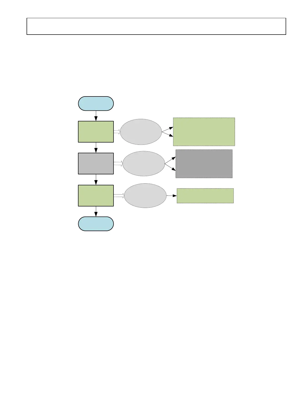
the user can safely shut down the device through TES. Figure 20 describes the high level flow of the device operation sequence and the
user interaction through TES.
START
Initialization
Normal Operation
Shutdown
END
User provides initialization
parameters to TES.
TES sets up the C structure
and calls API commands.
User adjust parameters on
the fly through TES.
User safely shuts down the
device through TES.
1: Analog Initialization APIs
2: Resources Loading APIs
3: Radio Initialization APIs
4: Initial Calibration APIs
5: Channel Prime APIs
Shut Down ADRV9001 API
API commands
...
Figure 20. High Level Flowchart of the Device Operation and User Interaction Through TES
As indicated in Figure 20, the purpose of this section is to provide user information about the initialization and shutdown process for the
ADRV9001 device utilizing the APIs developed by ADI. Figure 20 listed all high level operations used for initialization and shutdown
through one or a set of APIs. In the later sections, the major steps associated with each high level operation are further discussed. Note
with Software Development Kit (SDK) provided to the user, The ADRV9001 device can be initialized through the user’s own software
program independent of TES. However, the same API calling procedure described in this document should be followed.
Note all the information discussed in this section is subject to change over the time. It is not the intention of this section to explain every
related API function. Detailed information regarding the API functions can be found in the ADRV9001 Device API doxygen document.
In addition, this section does not describe API integration and the hardware abstraction Interface. Details of such can be found in the
Software Integration section. To find more details about the TES, refer to the Transceiver Evaluation Software (TES) section.
TES CONFIGURATION AND INITIALIZATION
The TES provides a Config tab that contains all the setup options for the ADRV9001. Under the Config tab, the user could configure
each channel of the device for a desired profile under the Device Configuration subtab, which sets high level parameters such as duplex
mode, data port sample rates and RF channel bandwidth. Then the user could further initialize the options used by the device during
startup under other subtabs, such as the carrier frequencies, ADC type and initial calibrations. Note GUI design could change
significantly over the time, see the ADRV9001 Evaluation System section for up-to-date information.
Based on the parameters set by the user, an initialization structure, adi_adrv9001_Init_t, is formulated by TES to contain all the required
settings to configure the device. This structure contains the system configuration setting, the system clock settings, transmit/receive data
structure settings and Programmable FIR filter settings. Please refer to the doxygen document for more details.
After all tabs are configured, the user must press the Program button in TES. This kicks off initialization programming. TES sends a
series of API commands that are executed by a dedicated Linux application on the platform. This initialization structure is passed to the
 Loading...