UG-1828 Preliminary Technical Data
Rev. PrC | Page 90 of 338
Digital Only and Phase Synchronization
Enabling MCS will guarantee the delay between the RF ports to SSI interface (or reverse direction) to be deterministic, across all
ADRV9001 devices. This ensures data will have deterministic delay (are synchronized) across all channels that have MCS enabled.
Additionally ADRV9001 also provide phase synchronization for the PLLs across multiple devices. User can choose to enable this option
so that not only the data are synchronized in time, but also the phase of the PLLs are also synchronized.
Note if choosing MCSMODE_DIGITAL mode, which does not guarantee phase synchronization, the process is done only once and that’s
after CALIBRATED state. This means after all MCS pulses are sent and all ADRV9001 components are synchronized, no more pulse is
needed. MCS is complete and no longer needs to run again unless chip is reset.
If MCSMODE_DIGITAL_AND_RFPLL_PHASE mode is selected, same as previous, MCS will be done at initialization stage and once
complete it will no longer require MCS pulses. After that phase synchronization will take place but this does not require MCS to rerun.
Whenever PLL changes, the phase sync will need to rerun to ensure the phase between all channels are synchronized.
To select one of the modes user can use the struct below:
typedef enum adi_adrv9001_McsMode
{
ADI_ADRV9001_MCSMODE_DISABLE = 0, /*!< Multi Chip Synchronization disabled */
ADI_ADRV9001_MCSMODE_DIGITAL, /*!< Multi Chip Synchronization for digital*/
ADI_ADRV9001_MCSMODE_DIGITAL_AND_RFPLL_PHASE /*!< Multi Chip Synchronization for digital and RFPLL phase */
} adi_adrv9001_McsMode_e;
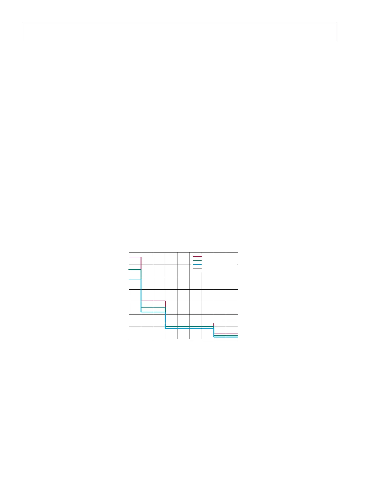
Frequency Hopping
In the case of frequency hopping, user can choose one of the options above, to enable MCSMODE_DIGITAL to have deterministic delay,
or to add additional phase synchronization. For the first option, user should only consider the PLL settling time, since there is no
additional phase synchronization required. For the second option, there will be additional time consumed and this depends on the
reference clock speed and the LO frequencies that user will use for frequency hopping.
Figure 84. PLL Phase Synchronization Time vs LO frequency and Fref
1500
1300
1100
900
700
500
300
100
100 200 300 400 500 600 700 800 900 1000
ACHIEVABLE LO PHASE SYNC TIME (
µs)
LO FREQUENCY (MHz)
24159-574
F
REF
= 400MHz
F
REF
= 350MHz
F
REF
= 360µs LINE
F
REF
= 300MHz
 Loading...