Preliminary Technical Data UG-1828
Rev. PrC | Page 93 of 338
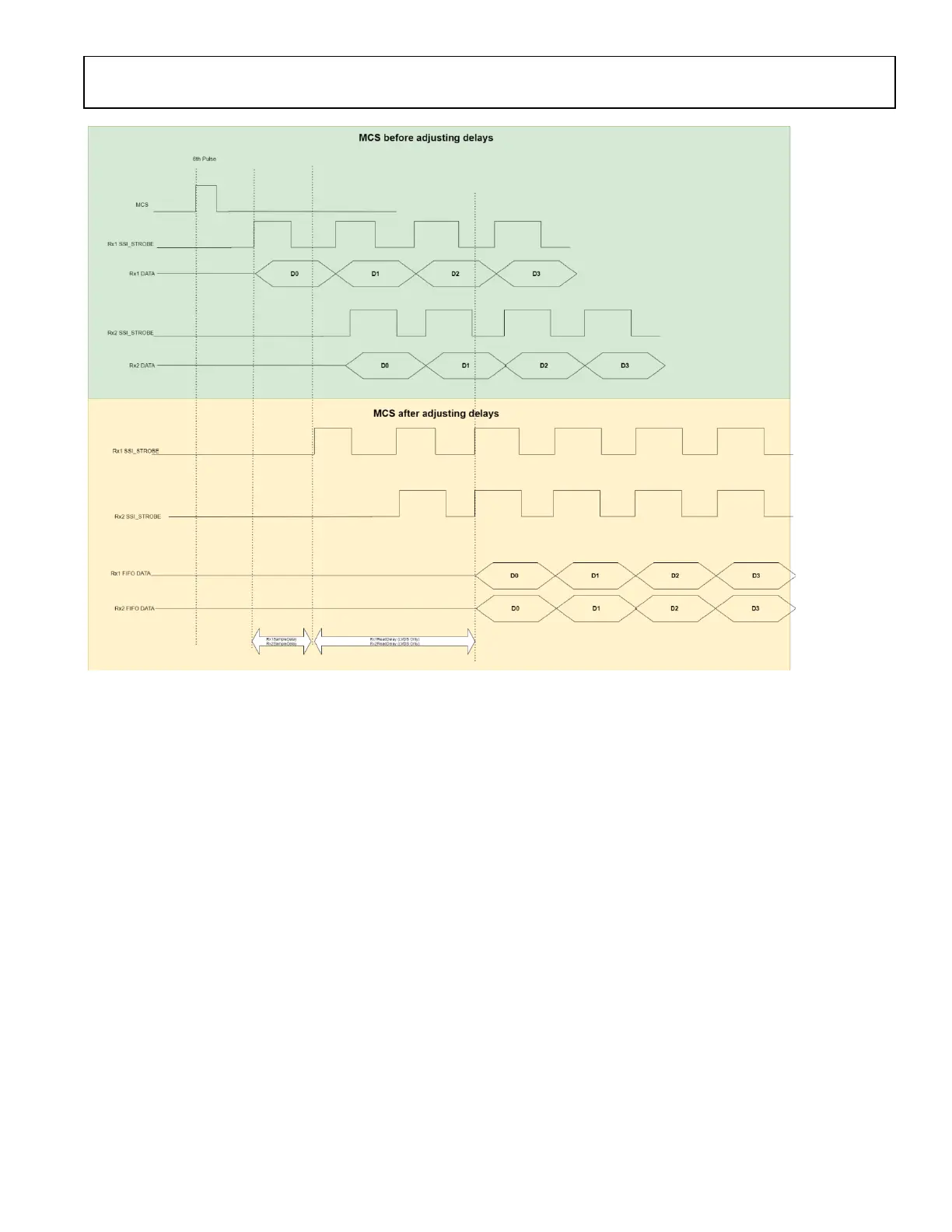
Figure 87 Rx MCS to Strobe Timing Diagram
User needs to calculate them in the following way:
Tx:
- Each channel is independent from other channels
o sampleDelay = MCS_to_Strobe latency – 1
o readDelay = 4
- Syncing Multiple channels: (ex. TX1 and TX2, or multiple Devices)
o sampleDelay = Min (all MCS_to_Strobe latency) – 1
o readDelay = Max (all MCS_to_Strobe latency) - Min (all MCS_to_Strobe latency) + 4
Rx:
- Each channel is independent from other channels
o sampleDelay = UserDefined
o readDelay (LVDS Only)= UserDefined (minimum of 1 to compensate for clock timing in LVDS from analog, imposed
by API)
- Syncing Multiple channels: (ex. RX1 and RX2, or multiple Devices)
o sampleDelay = UserDefined
o readDelay (LVDS Only)= UserDefined (minimum of 1 to compensate for clock timing in LVDS from analog, imposed
by API)
Once sample delay and read delay are calculated, user needs to set them by adi_adrv9001_Mcs_ChannelMcsDelay_Set.
 Loading...