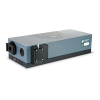
After tting, or replacing lters, it is good practice to synchronise the lter wheel hardware with the software interface.
To re-initialise the lter wheel, press the reset button on the lter wheel control graphic.
3.3.3
The optional lter wheel accessory is controlled by the Filter Wheel Control. This is described in more detail in.
1. The Filter Wheel Control indicates the currently selected lter and provides details of the lter at the bottom of the
control. The lter positions and their details are stored in non-volatile memory (EEPROM) in the instrument and
should be input by the user after a lter has been tted. To input (or modify) the details of a particular lter position
place the mouse cursor on the required lter position. Right click and a lter details input box will appear. Enter the
lter details (up to a maximum of 9 characters) and Left click when complete.
2. The operation of the lter wheel is very similar to that of the grating turret control. Positioning the cursor over each
lter position changes the cursor to a pointing hand and details about the lter are displayed.
Note: If the information is not automatically displayed, simply move the cursor out of the lter wheel control
box and then back onto the required lter to refresh the information.
3. To select a lter, simply position the mouse cursor on the required lter and LEFT click. The hardware responds
by rotating the lter wheel and the lter wheel graphic in the software control rotates to reect the change. The
accessory may be reset by clicking the reset button. On completion of a reset the lter wheel defaults to the Filter 1
position.
4. As the optical path difference will vary with the introduction of the lters into the beam path it may be necessary to
re-focus the spectrograph. This is achieved by adjusting the position of the detector. Please refer to Standalone
Spectrograph for details of adjusting the detector focus.
5. If the lter wheel assembly and/or the motorised slits assembly has been removed from the spectrograph body it
may be necessary to adjust the detector offset value stored in the spectrograph memory. Please refer to “Offset
Adjustment Control” on page 46 for further details of this function.

 Loading...