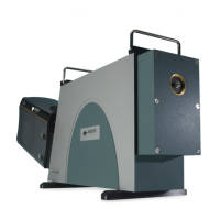
Screws are used for Roll and Tilt correction adjustment as shown below:
There are two pairs of adjustment screws for Roll, and for Tilt (shown above). Each pair of screws work in opposition to
each other, therefore for adjustment one should be loosened, then the other tightened. When you are happy with the grating
position they should be gently tightened against each other and the nal position re-conrmed. When one screw is tightened
the other may become loose, so it is best to go back and forth incrementally tightening them both.
Grating adjustment is an iterative process, and can be done with just a slit and any light source, such as a weak laser –
but ideally is performed using a bre input and a calibration light source. It is best to check the roll before the tilt (because
adjusting the roll may also affect the tilt.
The adjustment procedure is as follows:
1. Reset the wavelength drive (shown below) and set the wavelength drive to the ‘zero’ order position.
2. Acquire an image in real-time mode showing a non-saturated image of bre optic onto the sensor. If your system
has a shutter, set it to ‘Auto’ to acquire an image with no smearing during readout.
3. Use the offset adjustment on the Shamrock real-time control bar to move the image to the approximate horizontal
centre of the sensor, and make a note of the height (see image above).
4. Move to a wavelength, λ, at a higher grating angle. The control panel wavelength slider will show a red mark for the
maximum operating angle of 60°. For the best roll adjustment accuracy, move to an angle that is greater than half
this wavelength e.g. 400 nm is the maximum attainable wavelength for 800 nm, for a given grating. With low density
gratings you may need to use higher orders of calibration wavelengths, e.g. when using a 300 gpmm grating you
may wish λ to be the 8th order of the 546 nm mercury line (appearing at 4368 nm), which is a grating angle of 42°.
5. If the bre image is at the same height in the centre of the detector at the zero order and at the high wavelength,
then you do not need to make any adjustment to your grating.
6. Otherwise, remove the top plate, familiarise yourself with the adjustment screws on the grating, and if possible,
reduce your room lighting and use a cloth over the opening to help with the real-time adjustment of the grating
assembly while the camera is acquiring.
7. If the bre image height changes between the zero order and the high wavelength, then you need to adjust the roll of
the grating. Only make tiny adjustments with the push-pull screws before moving between 0 nm and λ nm to check
the effect. If the image is higher at λ than at the zero order, then loosen the inner push screw and tighten the outer
pull screw.
8. When the roll of the grating is satisfactory, adjust the tilt of the grating to centre the image vertically on the sensor.
If the image is too high, then loosen the pull screw (right of the 2 screws) and tighten the push screw (left of the 2
screws).
9. Repeat for other gratings on the turret.
If you experience any difculty with this procedure, please contact your local Andor Representative.
Detector offset
tab
Grating offset tab
Offset adjustment
buttons
Centre line button
 Loading...