25
SECTION 3
3. INSTALLATION PROCEDURES
3.1. INTRODUCTION
This section contains both installation instructions and initial adjustment/alignment procedures for the
ASR 11 S-band Antenna System. The instructions and procedures are for a typical system
configuration and should not vary from site to site. It is assumed that the following conditions have
been met:
The site preparation is complete including tower, access roads, power, lighting, building
foundations, etc.
A complete ASR 11 S-band Antenna has been delivered to the installation site.
A crane of sufficient capacity and of adequate height is at the site and is ready for use.
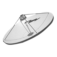
3.1.1 OVERVIEW - Refer to Figure 3-1.
The ASR 11 Primary Surveillance Radar (PSR) Antenna consists of a doubly curved parabolic
reflector with integral support structure, dual feedhom/polarizer assembly, R.F. waveguide and
control cables and all installation and interface hardware. The PSR antenna is designed for
continuous air traffic control radar operation within the terminal area supported atop an antenna
tower.
The reflector and feedhorns provide a modified cosecant squared elevation pattern with dual beam
receive capability providing enhanced high angle performance and minimum low angle ground
returns. Low and high beam polarizers provide switchable linear and circular polarization with both
target and weather ports.
The PSR antenna assembly consists of three main sub-assemblies plus one installation kit. These are
described as follows:
Reflector and Support Assembly (174115) - Refer to Figures 3-2 and 3-4
This is the main assembly which includes the reflector, back structure and antenna base. It is supplied
as one large assembly supported on shipping beams which are used both for lifting and as a support
stand.
Fixed Feeds Unit (174255) - Refer to Figure 3-4.
The fixed feeds unit includes the dual feed assembly (feedhorns and polarizers) and the feed support
boom shipped as a factory-aligned unit. The fixed feeds unit attaches to the antenna base with
locating pins eliminating the need for on-site adjustment of feed alignment. The assembly is shipped
in an enclosed plywood box.
 Loading...