02/08/2016 SDR-ASR11-052
TI 6310.59
74b
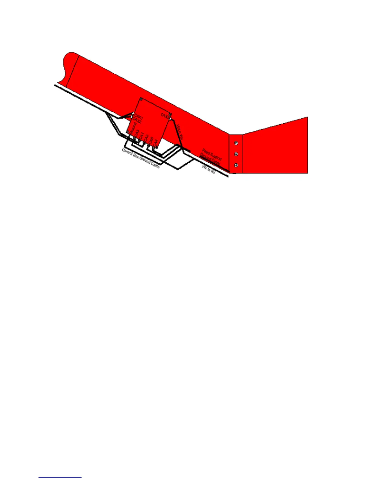
Figure 4b. Polarization and Beamswitch Control Box Close Up
f. Remove the old Polarization and Beamswitch Control Box by removing the four corner nuts attached to the
boom using ½ inch box-end and open-end wrench. Pull the Control Box including the mounting plate away
from the boom.
g. Install the new Polarization and Beamswitch Control Box using the same existing hardware. The new
mounting plate of the Control Box is mounted flush against the boom.
Note: Slide weather proofing over each cable before connecting.
h. Reconnect cables to the bottom of Control Box. Connect CA4 first and then weather proof CA5 next and so
on till all are connected. This will enable you to make sure everything is secure and water tight.
i. The cables CAX1 & 2 &3 can be connected either before or after the other cables because their weather
proofing is not as difficult.
j. Install the ground cables in same holes of the new box as removed from the old box.
k. Remove the Antenna Stow Pin and return to its stored position.
l. Remove lockout/tagout device from the Emergency Safety Switch inside the pedestal room.
m. Set the Emergency Safety Switch inside the pedestal room to the ‘On’ position. Place the polarizer
switch of the PLCP to the 1 or on position.
*
*
 Loading...