79
SECTION 5
OTHER EQUIPMENT
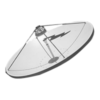
5.1 Test Antenna Kit - (Refer to figure 5-1 and Table 5-1)
Table 5-1
Test Antenna Kit
(174276)
Item
Part Number Description Qty.
1. 822062-1 Test Antenna 1
2. 9848-17 Screw, PH, 1/4-20 x .871g, 6
3. 9997-42 Washer, flat (1/4) 6
4. 9974-15 Washer, lock (1/4) 6
5.1.1 Electrical Check of Feed
A test antenna is provided to allow field testing of antenna circular polarization and to
measure transmitter power radiated by the antenna. To use the test antenna, the removable
circular section of the screen must first be removed from behind the reflector. The test
antenna is then mounted on the supports attached to the two center vertical contour plates.
WARNING
PERSONNEL SHOULD NOT BE ON THE ANTENNA LEVEL OF
THE TOWER WHEN TRANSMITTER POWER IS BEING
RADIATED BY THE ANTENNA.
5.1.2 Transmitter Power Measurement - These steps are followed to measure the transmitter power.
a. Connect the test antenna load to the through port of the directional coupler (part of the test
antenna), connect a power meter to the coupled port and rotate the test antenna to 0 degrees.
b. Place the power meter on the 10 mW scale.
c. Support the power meter on the reflector so that the meter can be viewed from the maintenance
level.
d. Select linear polarization for the antenna.
e. Turn on the transmitter but do not rotate the antenna.
f. Read the power meter in dBm.