User’s Manual for Node M and Node C
Network Elements
Page 26 M0121A4A.doc
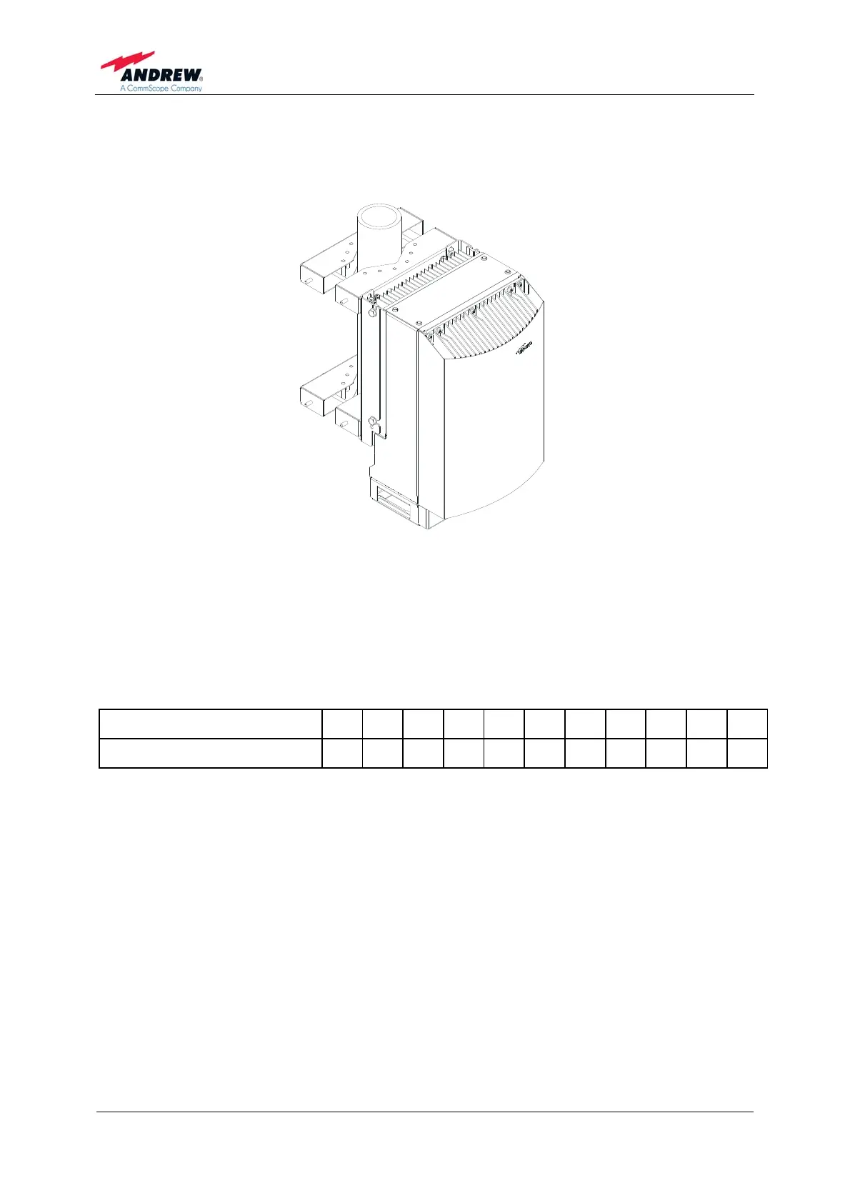
4.1.3. Pole Mounting Procedure
The following figure illustrates the pole mounting option back-to-back.
V14
A
figure 4-3 Pole mounted units
Before starting the mounting procedure, check the pole diameter of the pole to which
the units will be installed.
Then, cut the thread-bolts (see table 4-2 Components of pole mounting kit, pos. 5) to
the required length according to the following table:
Pole-diameter (mm) 100 110 120 130 140 150 160 170 180 190 200
Length of thread-bolt (mm) 216 226 236 246 256 266 276 286 296 306 316
table 4-1 Required length of thread-bolts