User’s Manual for Node M and Node C
Network Elements
Page 38 M0121A4A.doc
In the primary uplink path, a signal originating from the mobile is separated from the
downlink signal via the primary UL IN duplexer. It is then amplified by an integrated
low noise amplifier (LNA) and forwarded to the uplink digital channel module (DCM).
The DCM down-converts the signal to base-band, digitally filters it, amplifies it and
then up-converts it. In addition the interference cancellation technology is
implemented in the DCM. Finally, the signal is sent to the final amplifier (included in
DCM) and combined with the downlink input signal in the DL IN duplexer. The
optional diversity uplink path (via a second filter) is identical except signals enter via
the diversity UL IN duplexer and are combined in the DCM with the primary path.
In the downlink path, a signal originating from the base station is separated from the
uplink signal in the DL IN duplexer. It is then amplified by an integrated low noise
amplifier (LNA) and forwarded to the downlink digital channel module (DCM). The
DCM down-converts the signal to base-band, digitally filters it amplifies it and then
up-converts it. In addition the interference cancellation technology is implemented in
the DCM. Finally, the signal is sent to the final amplifier and combined with the uplink
input signal in the primary UL IN duplexer. The downlink DCM is also responsible for
communication and control of the entire unit.
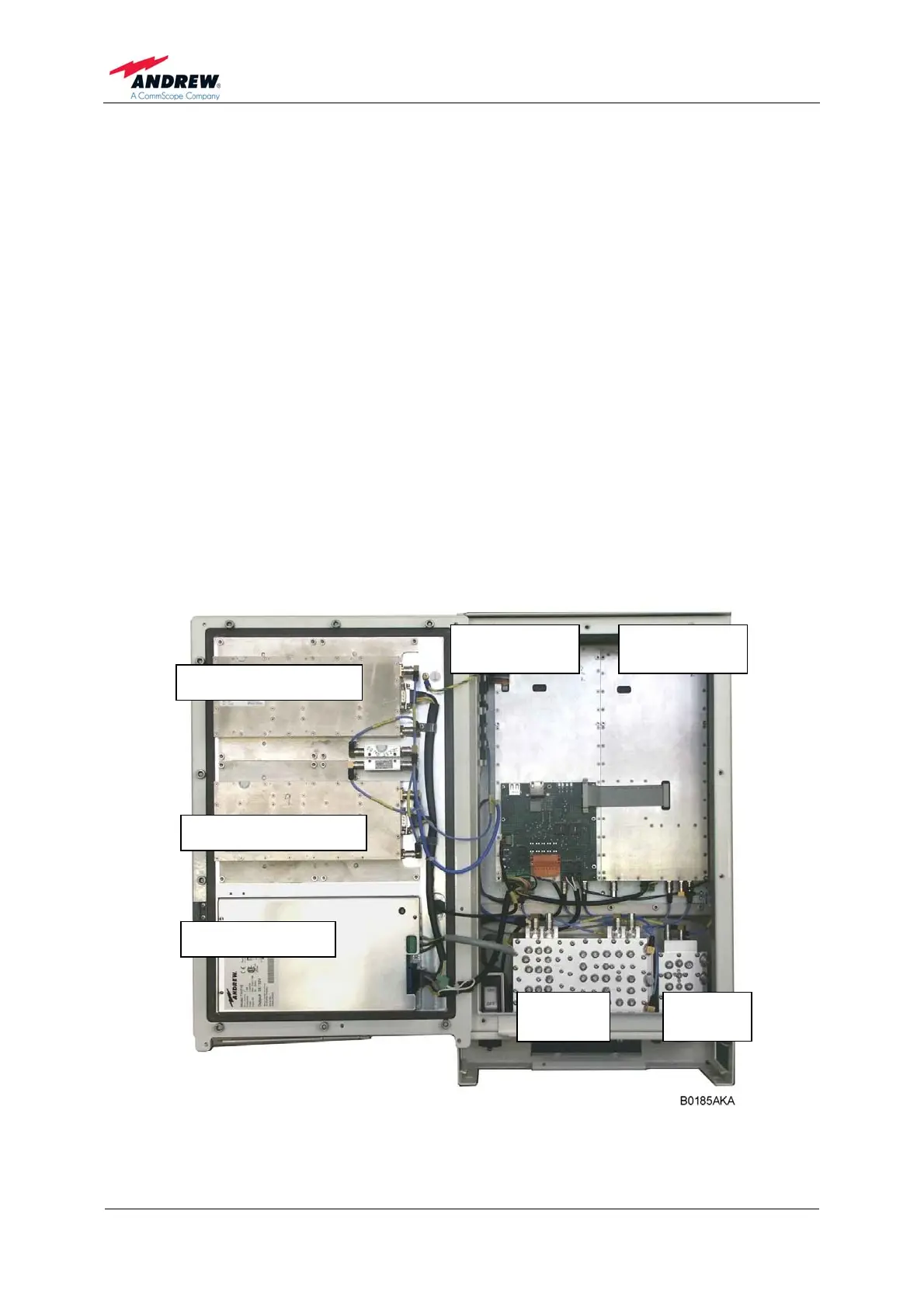
Using a Node C 843 as an example, the following figure illustrates the positions of
the RF components inside the Node M/C.
Digital channel
module DL
Digital channel
module UL
Downlink final amplifier
Downlink final amplifier
Power supply unit
Coverage
duplexer
Donor
duplexer
figure 5-2 RF path of a Node C 843, exemplary