User’s Manual for Node M and Node C
Network Elements
Page 54 M0121A4A.doc
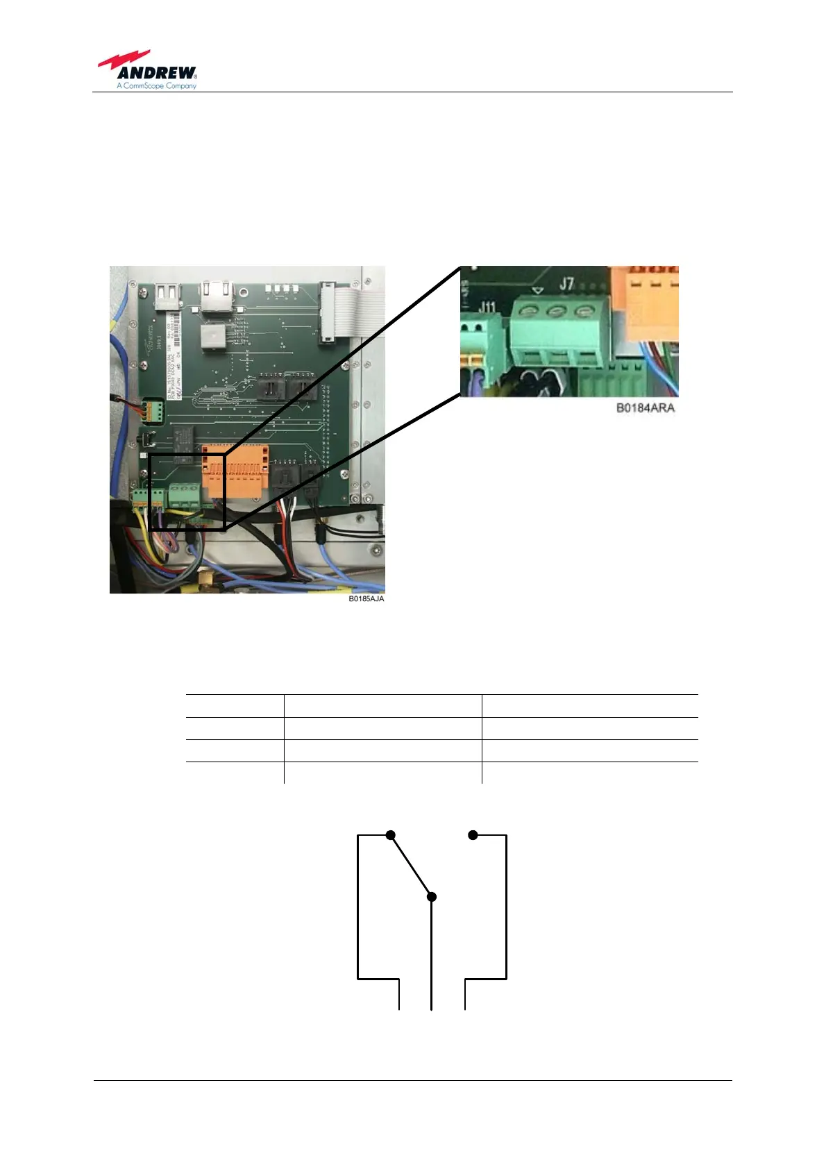
5.2.11.4. Summary Alarm
The summary alarm is a DC potential-free contact relay.
Observe that the cross-sectional area of the wires to be connected must be in the
range from 0.14 - 1.5 mm
2
.
Pin No: 1 2 3
figure 5-23 Summary alarm relay
The following table indicates the three-connector pin out.
Pin No Contact Maximum Resistive Load
1 Open in alarm condition Max 1 A @ 50 Vdc
2 Common Max 2 A @ 30 Vdc
3 Closed in alarm condition Max 1 A @ 230 Vac
table 5-1 Pin assignment of relay contacts
Pin 3 Pin 2 Pin 1
B0185AHA
figure 5-24 Relay contacts, alarm condition