5 Functional Description
Page 37
5. FUNCTIONAL DESCRIPTION
5.1. DIGITAL ARCHITECTURE
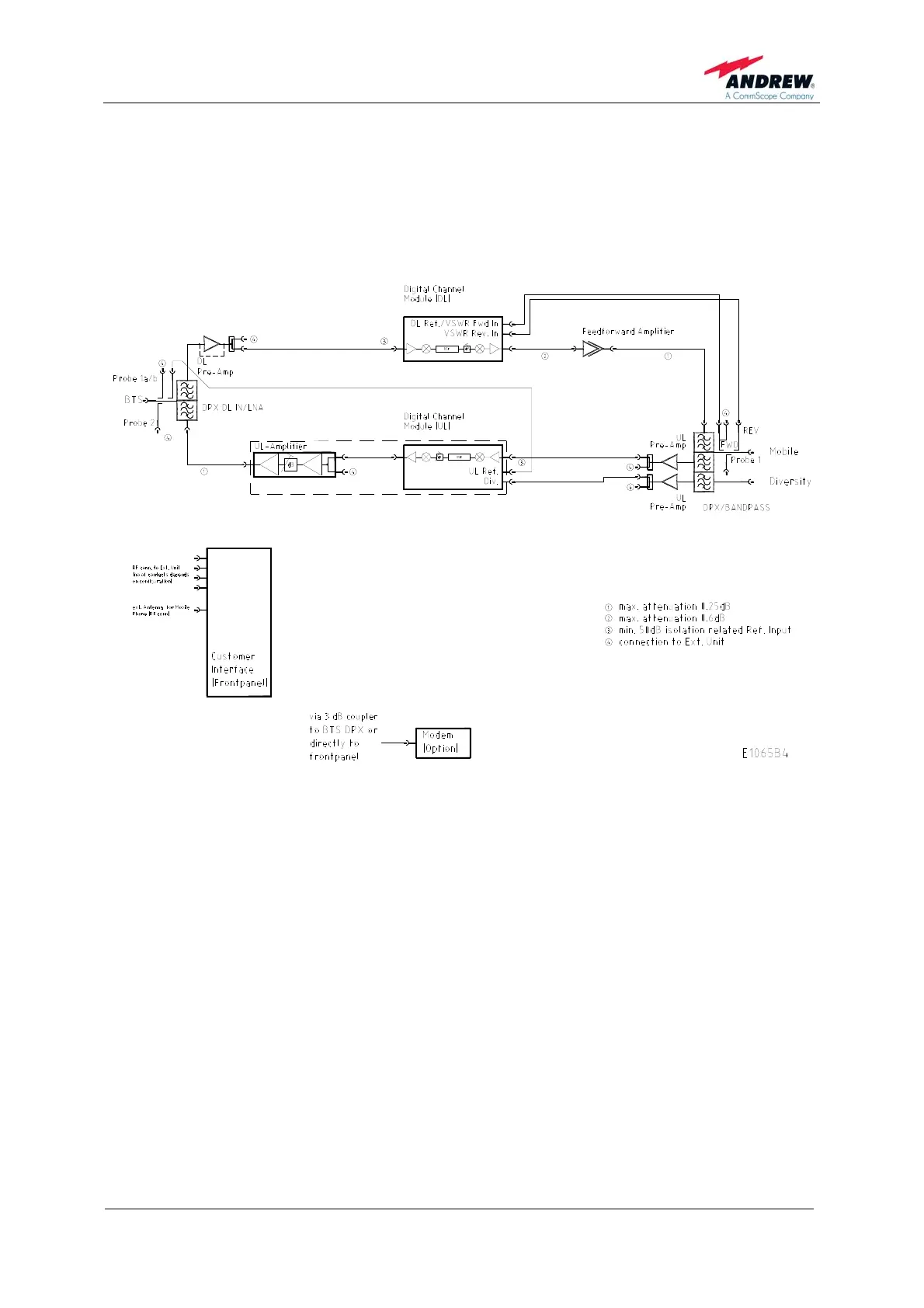
The following figure shows the RF block diagram of the Node M/C.
figure 5-1 Configuration of a network element
The Node M/C is designed to amplify signals between multiple mobiles and a base
station in a UMTS/CDMA system. The unit consists of a filter and amplifier chain in
the downlink and one or two filters and amplifier chains in the uplink (primary and
diversity). The uplink and downlink paths are connected via a duplexer on both ends
of each path.