User’s Manual for Node M and Node C
Network Elements
Page 52 M0121A4A.doc
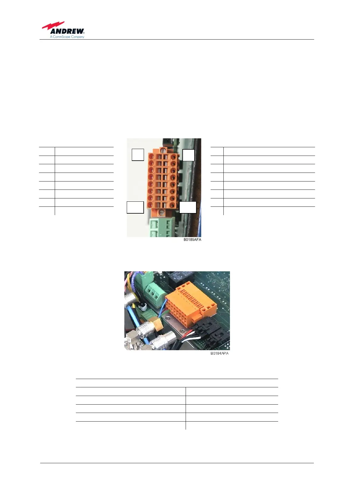
5.2.11.3. External Alarms
The external alarms are used to monitor the status of one or more external devices
via the Node M/C. A UPS or entry alarm is among the items that might be connected
to the contact relay and monitored via the Node M/C. The cage clamp connectors are
located on the EAC-board.
Observe that the cross-sectional area of the wires to be connected must be in the
range from 0.5 - 1.0 mm
2
. Do not use wire-end sleeves (wire cable ends).
2 n.c.
1 n.c.
4 GROUND
3 EXT_ALARM_3
6 GROUND
5 EXT_ALARM_2
8 GROUND
7 EXT_ALARM_1
10 PSTN_1_EXTERNAL
9 PSTN_1_INTERNAL
12 PSTN_2_EXTERNAL
11 PSTN_2_INTERNAL
14 GROUND
13 SUMMARY ALARM, LED GREEN
16 GROUND
15 SUMMARY ALARM, LED RED
figure 5-19 Pin assignment
1
2
16 15
figure 5-20 External alarm clamps, installed
External Alarms 1 to 3
Input voltage range 5 Vdc
Recommended input line Potential free
Nominal sink current to ground 15 mA
Active level High or low set via software
Connectors Cage clamps