CNC Motion Setup/Testing Utility
P/N 70000635C
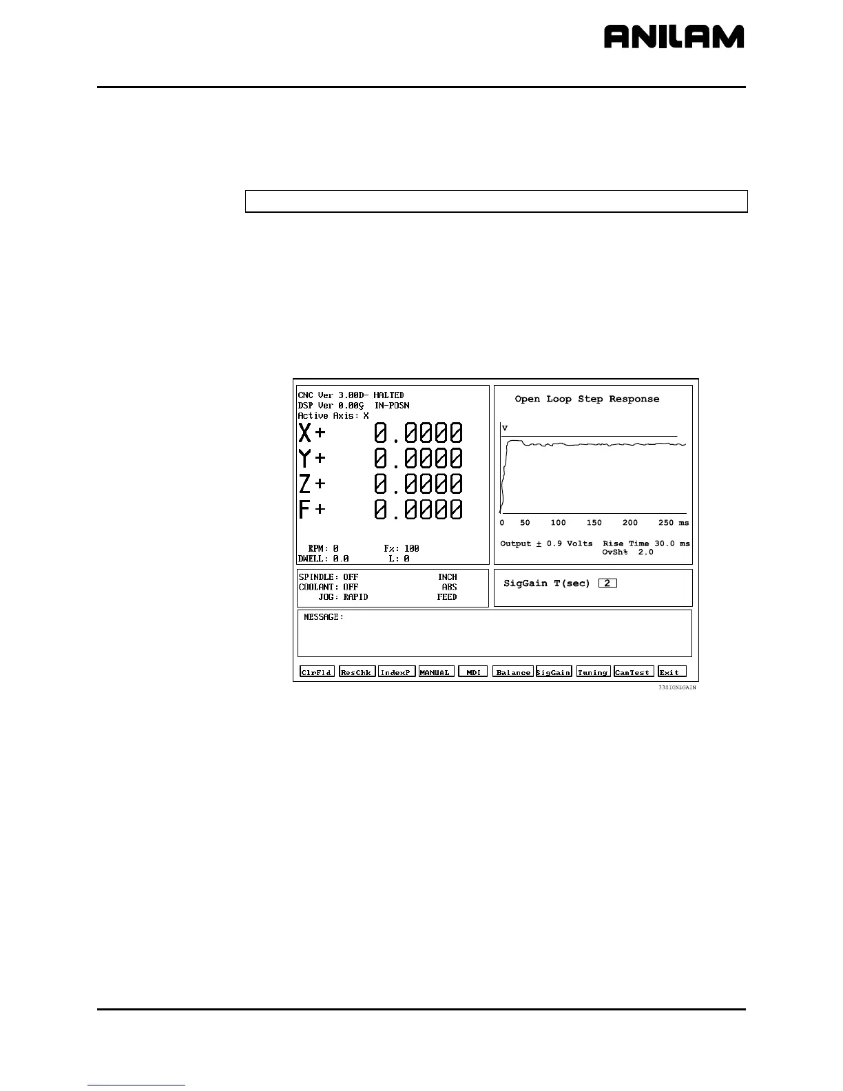
• T is the amount of time in seconds that the axis will travel in one
direction before it reverses for the same amount of travel in the
opposite direction. The actual distance depends on the feedrate
that corresponds to 0.9V.
NOTE: Press ClrFld (F1) to erase the entry and enter another number.
4. Press START. The CNC generates an open loop step response,
including rise time, in the Graph Area of the screen.
5. Adjust the signal gain pot until the displayed feedrate is at 10% of the
machine’s maximum Rapid speed, using the fastest axis. (The
maximum rapid speed is set by the machine builder in the Setup
Utility.)
6. Press MANUAL (F4) to cancel the test.
Figure 11, Signal Gain (SigGain) Screen, DC Systems
If the system is equipped with an ANILAM Servo Amplifier Board, all of
the voltage measurements can be made with the Servo Drive Test Board.
Measure command voltage across TP1 and TP2 of the test board. These
signals can also be found on Pins #3 and #11 of J1.
Measure the tachometer output across TP2 and TP3 of the test board.
These signals can also be found on Pins #5 and #11 of the J1 input
connector on the ANILAM Servo Amplifier Board.
All rights reserved. Subject to change without notice.
November 2009
19