CNC Motion Setup/Testing Utility
P/N 70000635C
All rights reserved. Subject to change without notice.
November 2009
11
Test Points
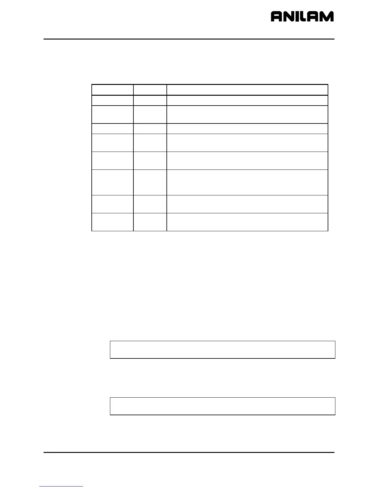
Refer to Table 3 for a description of test points and signals.
Table 3, Servo Drive Test Board: Test Points and Jumpers
Test Point Pin Signal
TP1 3
Command Signal
TP2 4
Common for all servo signals and potentiometers.
All readings are referenced to TP2.
TP3 5
Tachometer
TP4 6
Motor Current output monitor. The scale factor is
1V = 5A.
TP5 9
Clamp input from the SCB. When pulled to chassis
ground, the servo’s output is forced to 0 VDC.
TP6 10
Fault output. When the servo card is faulted, the
output is pulled low. If TP6 is pulled to chassis
ground, the Servo is disabled and coasts to a stop.
JMP1 11
Command Signal Common. If removed, JMP1 will
open the common line at Pin 11 of J1.
JMP2 3
Common Signal. If JMP2 is removed, the
Command signal will open at Pin 3 of J1.
Jumpers
While troubleshooting, you can remove jumpers to isolate the Servo Drive
from the DAC outputs of the Motion Control Board during troubleshooting.
If Pin 2 of JMP1 and JMP2 are shorted together, the Servo Drive’s input
is fixed at 0 VDC; this can be useful in troubleshooting balance problems.
Balancing the DSP
2
Board (F6)
On systems that use an ANILAM Servo Amplifier Board, P/N 33000039 or
33000123 (see Figure 8 (5 LEDS), DC Systems or Figure 9 (1 LED),
DC Systems), measurements for this procedure can be made at the J1
input connector with the Servo Drive Test Board, P/N 33000102.
NOTE: If ANILAM did not provide the servo amplifiers, follow the
guidelines for balancing supplied by the manufacturer.
Refer to Figure 7, ANILAM DSP
2
Board Balance Pots, P/N 33000413,
DC Systems. Measure command voltages across TP1 and TP2 of the
test board.
NOTE: These signals can also be found on Pin #3 and Pin #11 of the J1
input connector on the ANILAM Servo Amplifier Board.
All DSP
2
Boards are adjusted at the factory and should be within limits.
Only balance the DSP
2
Board if it is not at 0 VDC (±0.001V).
 Loading...