CNC Motion Setup/Testing Utility
P/N 70000635C
All rights reserved. Subject to change without notice.
November 2009
21
Test Board Installation
IMPORTANT: Press E-STOP to de-energize servos before installing the
test board.
1. Remove the cable attached to J2 of the Servo Amplifier you wish to
monitor and connect it to P1 of the test board.
2. Attach W1 of the test board to J2 of the servo.
3. Re-energize the servos.
Test Points
Refer to Table 6 for a description of test points and signals. For AC
brushless systems with differential DSP
2
boards, use TP1 and TP3. For
the earliest AC systems with single-ended DSP
2
boards, use TP1 and
TP2.
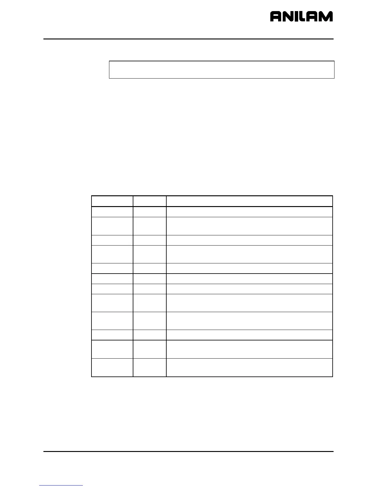
Table 6, Servo Amplifier Test Board: Test Points and Jumpers
Test Point Pin Signal
TP1 1
Command Signal +
TP2 3
Common for all servo signals and potentiometers.
All readings are referenced to TP2.
TP3 2
Command Signal –
P2-1 4
Motor Current output monitor. The scale factor is
1V = 7.5A.
P2-2 5
Analog Out
P2-3 6
+Limit In
P2-4 7
–Limit In
P2-5 8
Clamp input from the SCB. When pulled to chassis
ground, the servo’s output is forced to 0 VDC.
P2-6 9
Fault output. When the servo card is faulted, the
output is pulled low.
P2-7 3
Common
JMP1 1 Signal. If JMP1 is removed, the Command signal
will open at Pin 1 of J1.
JMP2 3 Common. If removed, JMP2 will open the common
line at Pin 3 of J1.
Jumpers
While troubleshooting, you can remove jumpers to isolate the Servo
Amplifier from the DAC outputs of the Motion Control Board during
troubleshooting. If Pin 2 of JMP1 and JMP2 are shorted together, the
Servo Amplifier’s input is fixed at 0 VDC; this can be useful in
troubleshooting balance problems.
 Loading...