58
03/2010 Rev. 0.1
03/2010 Rev. 0.1
59
1.1 Boiler System
Turn on the device using the ON/OFF switch. The display will light up.
The magnetic valve ( g. 1-10) will open and the hot water reservoir ( g. 1-9) will be lled to the
maximum electrode. The heating element will be switched on. The display shows [ boiler lling ] and
[ boiler heating ]. As soon as the NTC sensor measures the set temperature, the heating element will
be switched off.
When a drink is being dispensed the water level drops and the maximum electrode is released;
the inlet valve (2.5 litres/min.) opens and immediately re lls the reservoir until the maximum level
is reached again. If the water level falls under the minimum electrode level during operation, the
operating panel display will show [re lling boiler]. If the supply of water is not restored within 90
seconds, the display will show the error message [E3 level error] and shut off the inlet valve.
1.2 Temperature regulation
The heating element is turned on when the water temperature falls below the temperature setting and
the minimum electrode registers water. The temperature in the water reservoir is measured using an
NTC precision sensor mounted on the outside wall of the reservoir.
The water temperature also drops when drinks are dispensed. To avoid the temperature regulator from
responding too late, the heating element is switched on as soon as the inlet valve ( g. 1-10) opens
and cold water is added. The heating element switches off again as soon as the inlet valve shuts
off. The software can also be used to delay when the heating element switches off. See menu item
2.4 Settings / Temperature in the service menu. The heating element always switches off when the
maximum boiler temperature of 99C is reached.
1.3 Hot water dispensing
When dispensing drinks one of the dispensing valve ( g. 1-8) opens and hot water ows to the brewer
or mixer system. The ow velocity for each valve is set using the adjustment screw on the valve. The
amount of out ow is determined by the length of time that the valve stays open. In order to rinse the
brewer unit and mixer system, a small amount of rinsing water is released shortly after dispensing to
rinse away any ingredient residue.
1.4 Ingredients and mixer system
The ingredients canisters ( g. 1-11) are powered by a 130RPM motor ( g. 1-12). The instant product
(ingredient) is forced out of the canister by a coil and drops through the dispensing bent pipes into the
mixer unit ( g. 1-17). At the same time, the dispensing valves ( g. 1-18) dispense hot water into the
mixer unit. The mixer motor ( g. 1-15) blends the instant product with water at a speed of 10,700 RPM
using the mixer rotor ( g. 1-16). The drink ows into the cup via the drink outlet ( g. 1-3). All individual
parts mentioned in this section can be sequentially coordinated using adjustable
parameters (timers) in the control unit.
1.5 Evaporation extractor system
Evaporation released during mixing is largely absorbed by the evaporation extractor ring ( g. 1-18)
and sucked into the machine via the lter cassette ( g. 1-14). The evaporation and ingredient residue
are absorbed by the lter. The lter ( g. 1-14) can be easily reached (for cleaning purposes) by
dismantling the mixer unit ( g. 1-17). To a large extent, this prevents evaporation from entering the
canister outlet and making ingredients damp.
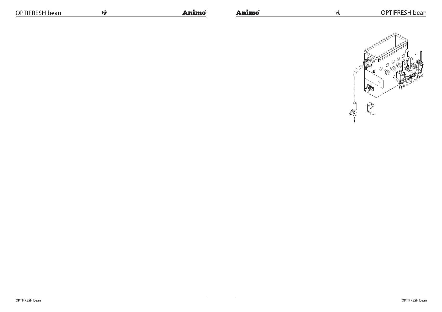
1.6 Solid State Relay (SSR)
The heating element is controlled by a solid state
relay, which supersedes the magnetic switch that was
formerly used for this purpose.
1.7 Steam thermostat
The solid state relay (SSR) is secured by a steam ther-
mostat which is build in line with the over ow tube.
The steam thermostat contact is in series with the solid
state. This thermostat prevents the boiler from boiling
empty when the solid state breaks down in a operating
condition.
The thermostat switches the heating element OFF
when steam escapes from the boiler. The thermostat
must be manually reset.
Fig. 2
SSR