UNION SWITCH & SIGNAL Microlok II System Startup, Troubleshooting, and Maintenance
4-46 September 2000 SM-6800C Rev. 2.5
4.12.5 Enabling, Disabling, and Configuring Printed Circuit Boards
The system configuration selection display provides a number of selection buttons that enable the
configuration of the Microlok II system printed circuit boards. Buttons are only provided on this
display for circuit boards that are properly defined in the application software.
NOTE
This section provides a general overview of circuit board configuration using the Tools
program. Refer to chapter 6 for specific details on configuring the individual types of
Microlok II printed circuit boards.
For the majority of the Microlok II I/O circuit boards, you can only set the enabled/disabled state
of the board and enable/disable the selective shutdown feature for the board. The coded track
circuit boards and lamp driver boards have additional configuration parameters that must be set.
These boards are covered in detail in chapter 6.
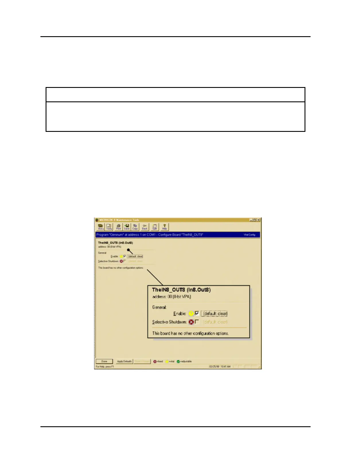
The following is an example of a simple board configuration. The mixed vital I/O board is used
in this example. To configure a standard vital output board, click on one of the In8_Out8
selection buttons on the system configuration selection screen. A window similar to the one
shown below will appear.
 Loading...