UNION SWITCH & SIGNAL Microlok II System Startup, Troubleshooting, and Maintenance
6-32 September 2000 SM-6800C Rev. 2.5
6.2.15 Signal Lamp Adjustments
The configuration of the signal lamp circuits is a two step process. This involves checking the
configuration of the installed lamp driver boards and setting the voltage/current supplied to each
signal lamp driven by the Microlok II system.
6.2.15.1 Configuring the Vital Lamp Driver Boards (Lamp16)
There are three parameters that can be set for each vital lamp driver board. These are the
enabled/disabled board status, the wattage of each signal lamp associated with the board, and the
lamp diagnostic mode associated with each lamp. Use the following procedure to configure the
vital lamp driver boards:
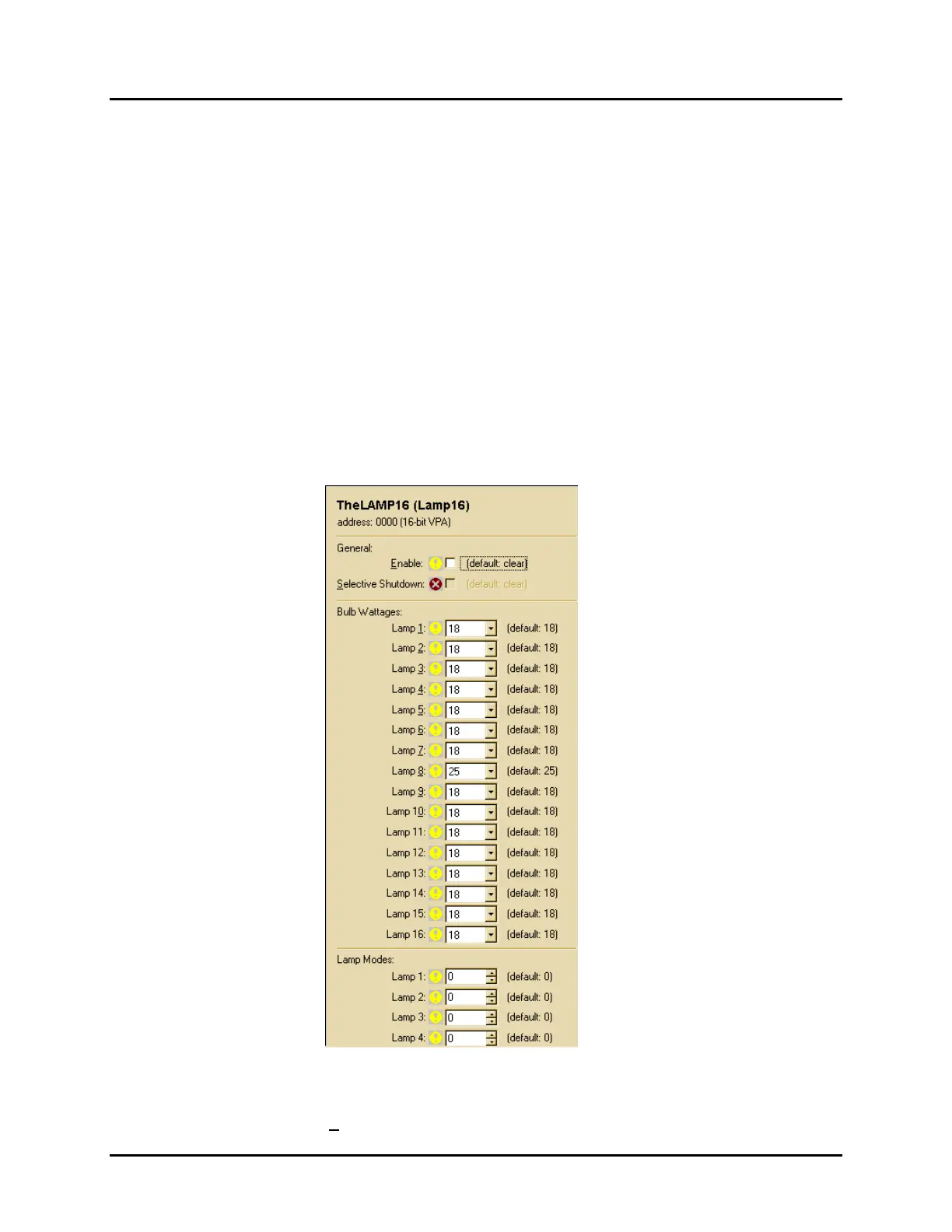
1. With the system configuration selection screen displayed on the laptop computer, click on
one of the Lamp16 selection buttons. A configuration screen similar to the one shown below
will be displayed. This screen shows the current configuration of the selected board,
including the system default settings.
2. First, make sure that a check mark appears in the
Enable selection box at the top of the
screen. You cannot make any other adjustments to the board parameters if it is not enabled.
If necessary, click on the
Enable selection box to insert a check mark.
 Loading...