Microlok II System Startup, Troubleshooting, and Maintenance UNION SWITCH & SIGNAL
SM-6800C Rev. 2.5 September 2000 2-11
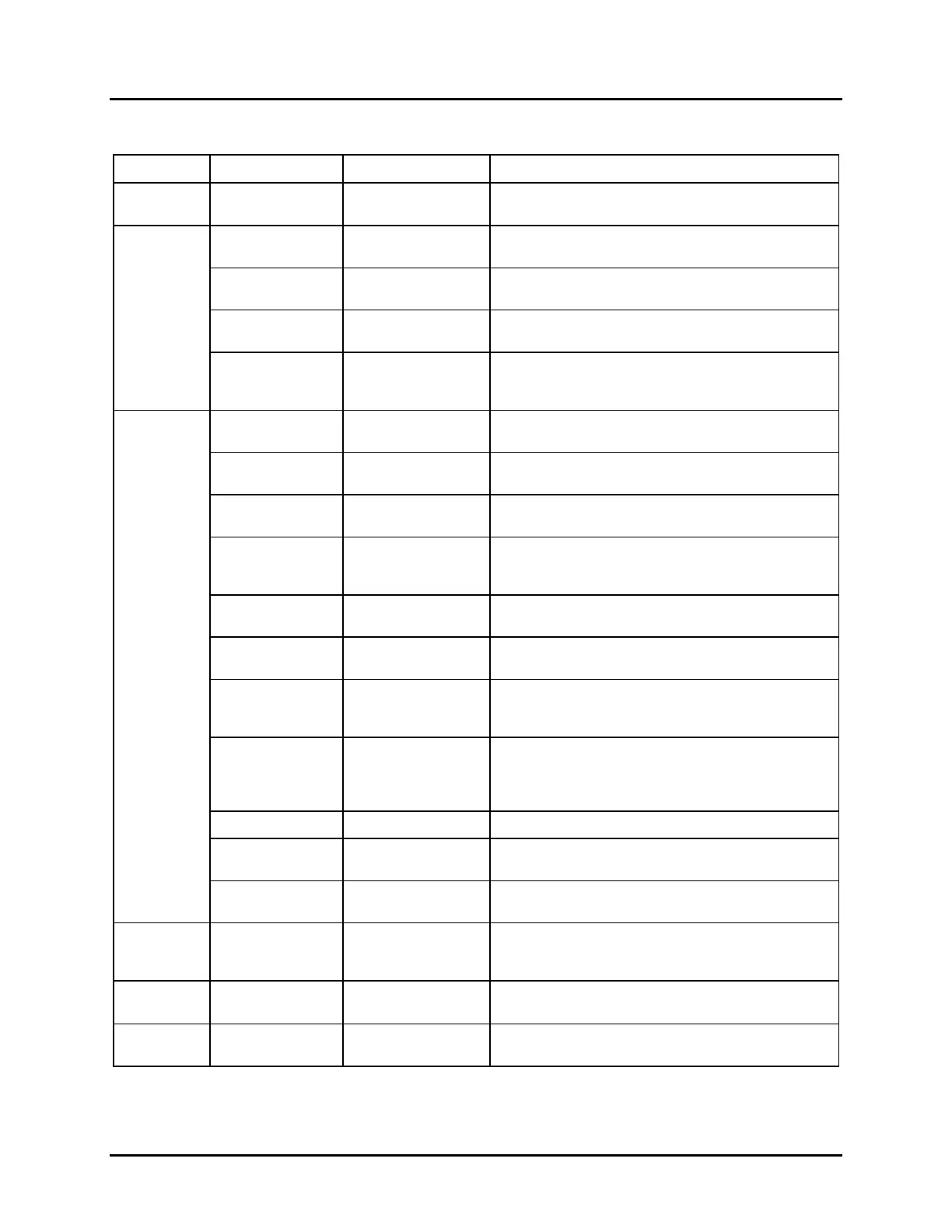
2.10 CODE SYSTEM INTERFACE PCB (Figure 2-7)
Fig. 2-7 Ref Label Device Purpose
1 (none) 4-character alpha-
numeric LED display
Displays on-unit configuration menu and options.
2
1 PORT 1 RXD
red LED Flashes when serial port 1 is receiving data.
Otherwise, this LED is off.
2 PORT 2 RXD
red LED Flashes when serial port 2 is receiving data.
Otherwise, this LED is off.
3 MSTR RXD
red LED Flashes when the Master port is receiving data from
the Slave unit. Otherwise, this LED is off.
4 DIAG RXD
red LED Flashes when the diagnostic port is receiving data
from the connected laptop computer. Otherwise, this
LED is off.
3
5 SLV DATA
red LED 50 millisecond flash when the Slave port receives
good data. Otherwise, this LED is off.
6 SLV XMT
red LED Flashes on when the Slave port transmits good data.
Otherwise, this LED is off.
7 SLV ADDR
red LED 50 millisecond flash when the Master unit correctly
addresses the Slave port. Otherwise, this LED is off.
8 SLV ERR
red LED This LED is on steady when the Slave port receives
bad data from the Master unit. This LED goes out
when the Slave port receives good data.
9 MSTR DTA
red LED 50 millisecond flash when the Master port receives
good data. Otherwise, this LED is off.
10 MSTR XMT
red LED Flashes on when the Master port transmits good
data. Otherwise, this LED is off.
11 MSTR ERR
red LED This LED is on steady when the Master port receives
bad data from the Slave unit. This LED goes out
when the Master port receives good data.
12 DIAG ERR
red LED This LED is on steady when the diagnostic port
receives bad data from the laptop computer. This
LED goes out when the diagnostic port receives
good data.
13 RESET
red LED When lit, indicates that the CPU is in the reset mode.
14 WATCHDOG
red LED Flashes at a 2 Hz rate when the board is functioning
properly.
15 DELIVER
red LED Flashes when delivering outputs to GENISYS or
Microlok-Plus output boards.
4
SELECT
2-pos. toggle switch
(return-to-center
type)
Used to select on-unit configuration items from menu
as shown on 4-character alphanumeric display.
5
EXECUTE
Momentary
pushbutton.
Used to enter configuration item selected with
SELECT toggle switch.
6
RESET
Momentary
pushbutton.
Used to reset the code system interface board.
 Loading...