UNION SWITCH & SIGNAL Microlok II System Startup, Troubleshooting, and Maintenance
6-24 September 2000 SM-6800C Rev. 2.5
6.2.14 Cab Signal Adjustments
Setting up the cab signal track circuits is a four-step process. This process involves:
• Checking/adjusting the configuration of the coder output printed circuit board.
• Setting the cab signal rail current by installing the appropriate jumpers.
• Fine-tuning the rail current level.
• Setting the cab signal current limiting adjustment.
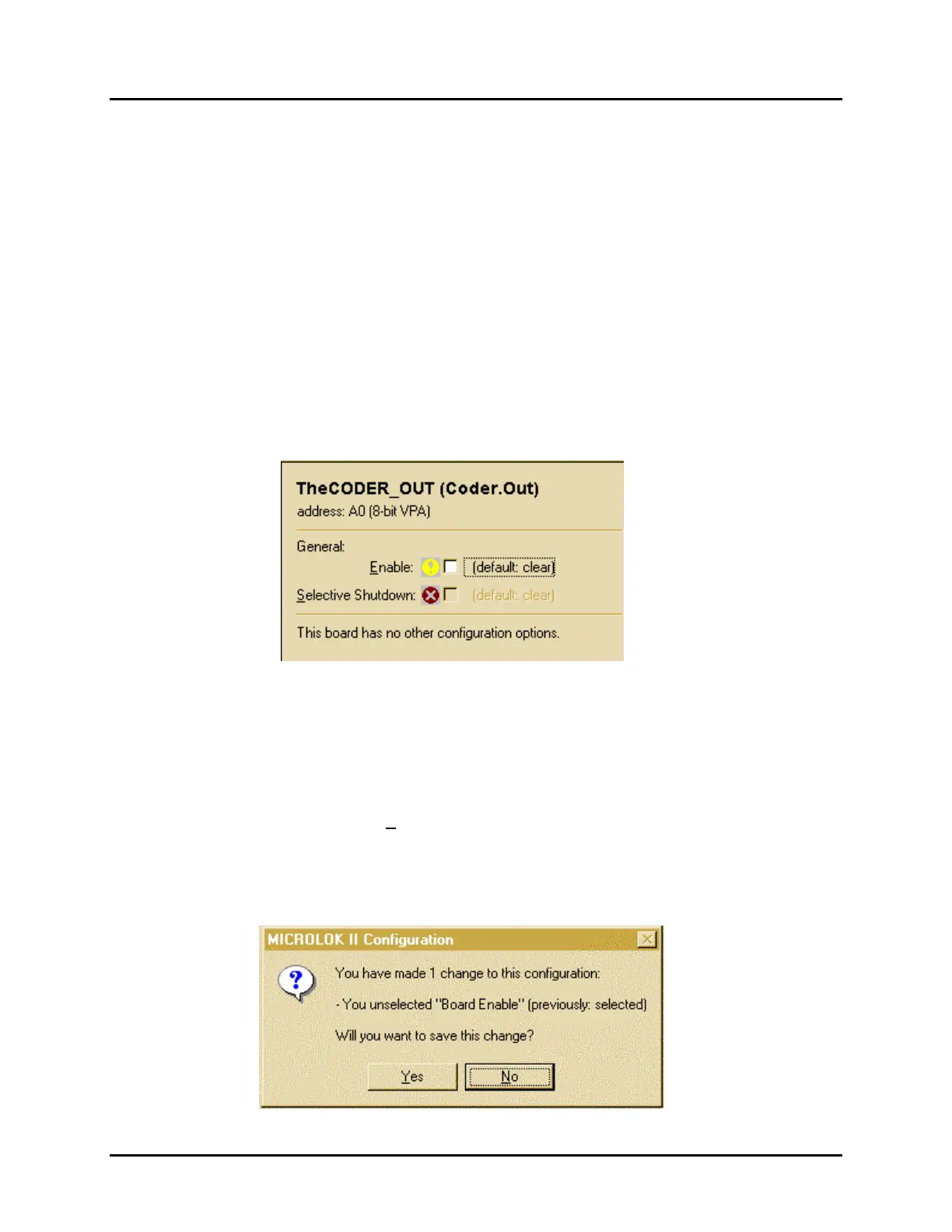
6.2.14.1 Configuring the Coder Output Boards (Coder.Out)
To configure a coder output board, click on one of the Coder.Out selection buttons on the system
configuration selection screen. A dialog box similar to the one shown below will appear.
The only configurable option for the coder output board is the Enable option. Selective
Shutdown
is not yet implemented and will remain disabled. Enable is user configurable through
the Tools program only if it is identified as an adjustable parameter in the application software.
Use the following procedure to configure the coder output board:
1. First, make sure that a check mark appears in the
Enable selection box at the top of the
screen. If necessary, click on the Enable selection box to insert a check mark.
2. When Enable has been set to the proper value for the application, click on the Done button at
the lower left corner of the screen. A dialog box similar to the one shown below will be
displayed:
 Loading...