Microlok II System Startup, Troubleshooting, and Maintenance UNION SWITCH & SIGNAL
SM-6800C Rev. 2.5 September 2000 2-1
2. SYSTEM CARDFILE CONTROLS AND INDICATIONS
Before you can set up and configure the Microlok II system, you should become familiar with the
front panel controls and indications associated with the Microlok II system printed circuit boards.
Sections 2.1 through 2.15 that follow provide an introduction to the functions associated with
each control and the information provided by each indicator on the Microlok II circuit boards.
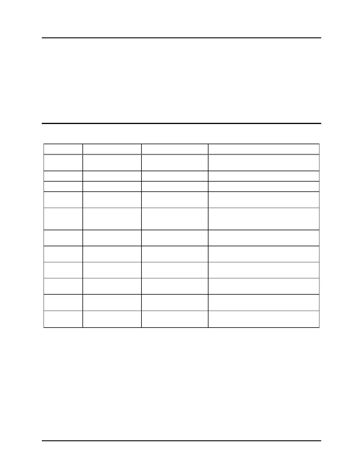
2.1 CPU PRINTED CIRCUIT BOARD (FIGURE 2-1)
Fig. 2-1 Ref Label Device Purpose
1, 2 (none) 4-character alpha-
numeric displays
On-site configuration programming menus
and options
3
A, B, C, D, E
yellow LEDs Reserved for serial link status
4
1, 2, 3, 4, 5, 6, 7, 8
red LEDs User-defined in application software
5
ON LINE
green LED When lit, indicates normal system operation
(successful diagnostics)
6
VPP ON
yellow LED When lit, indicates FLASH +5V or +12V
programming voltage enabled (via board
jumper).
7
RESET
green LED When lit, indicates that the system is in
reset mode.
8
RESET
Momentary pushbutton When pressed, resets the CPU. Also used
to place the CPU in the reset mode.
9
MENU L-R
3-position (return-to-
center) toggle switch
Used to search main program menu items
shown on displays.
10
MENU UP-DOWN
3-position (return-to-
center) toggle switch
Used to select main program menu items
shown on displays.
11
ADJUST UP-DOWN
3-position (return-to-
center) toggle switch
Used to cycle through configuration values
to be selected with ACTION switch.
12
ACTION ACCEPT-
REJECT
3-position (return-to-
center) toggle switch
Executes or cancels configuration value
selected with ADJUST switch.
 Loading...