LCD-80 ACS Mode EIA-485 Connections Annunciators
IQ-301 PN 50036:F 10/29/2001 145
C.6 LCD-80 ACS Mode EIA-485 Connections
Refer to the LCD-80 Manual
for additional information.
This section shows how to install LCD-80s set to ACS Mode to the control panel,
subject to the following:
• Maximum number of LCD-80s allowed – A maximum of four LCD-80s may be
connected when powered by the control panel. If, however, the LCD-80s are
powered by a separate UL-listed power supply, up to 32 may be connected.
• Maximum distance – There is a 6,000 foot (1828.8 m) maximum distance (16
AWG) between the control panel and the first or last LCD-80 and between each
LCD-80.
• Cable – Use overall foil/braided-shield twisted pair cable with a characteristic
impedance of approximately 120 ohms.
• Circuit rating – The EIA-485 circuit is rated 5.5 VDC max., 60 mA max.
• Connections – All connections are power-limited and supervised.
This section shows how to install LCD-80s set to ACS Mode to the control panel,
subject to the following:
Connect the EIA-485 circuit as follows:
1. Connect each LCD-80 to 24 VDC operating power (power-limited and supervised)
to the AUTOPULSE IQ-301 as shown in Figure 139 on page 146.
2. Set SW2 on the control panel to the “ACS” position (right position).
3. Set the LCD-80 start address to 01.
4. On the LCD-80, set switch SW2 to “1”, and set SW3-1 and SW3-2 to “OFF”.
5. Set the LCD-80 to a size of 128 points.
6. To use a 40-character display; set SW5 OFF and SW6 ON. To use a 20-character
display; set SW5 ON and SW6 OFF.
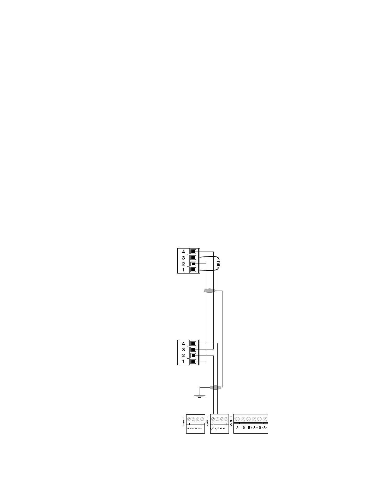
Figure 137 LCD-80 ACS Mode EIA-485 Connection
Install 120 ohm
terminating resistor on
last LCD-80
first LCD-80
EIA-485 In (–)
EIA-485 Out (–)
EIA-485 In (+)
EIA-485 Out (+)
EIA-485 In (–)
EIA-485 Out (–)
EIA-485 In (+)
EIA-485 Out (+)
last LCD-80
TB5-1 (+)
TB5-2 (–)
P2
P2
 Loading...