Components System Overview
IQ-301 PN 50036:F 10/29/2001 15
:
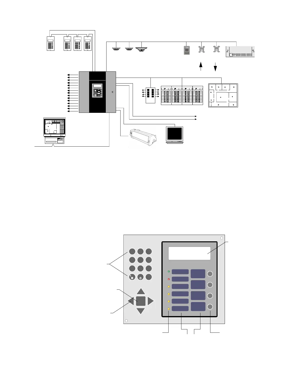
Figure 1 IQ-301 System Features
1.3 Components
1.3.1 Membrane Switch Panel
Figure 2 shows the membrane switch panel which includes the following:
• Windows for the Liquid Crystal Display (LCD) and six system status indicator
LEDs.
• Programming keys, including a 12-key alphanumeric pad (similar to a telephone
keypad) an
ENTER
key, and four arrow movement keys.
• Slide-in labels, which provide switch and LED description for the six system status
indicator LEDs and the four operator keys.
Figure 2 Membrane Switch Panel
LCD-80 Remote Display/Control
(up to 32 devices)
Signaling Line Circuit (SLC) up to 198 devices
XP Transponder
Monitor Control
Module Module
NBG-12LXFSP-751 FSI-751 FST-751
IDC NAC
Annunciator control points
Up to 68 fully
programmable
output circuits
Dual phone lines to
Central Station
To ot h er
FACP
CRT terminal
LDM-32 custom graphics
ACM-8R
EIA-232 terminal
ACM/AEM-16AT annunciator
Optional 396-channel UDACT
ACS EIA-485
EIA-485
PRN printer
IQ-301
ENTER
ACKNOWLEDGE
STEP
ALARM
SILENCE
DRILL
HOLD 2 SECOND S
SYSTEM
RESET
AC POWER
FIRE
ALARM
PRE-ALARM
WAR NING
SUPERVISORY
ALARM
SILENCE
SYSTEM
TROUBLE
DET MOD
12
3
4
5
6
7
89
#
A
B
C
D
E
F
G
H
I
J
K
L
M
N
O
P
R
S
T
U
V
W
X
Y
Q
Z
-
/
.
ALL SYSTEMS NORMAL
09:45A THU 06/18/97
Slide-in labels
System status
indicator LEDs
Four
operator keys
ENTER
switch
Cursor movement keys
12-key alphanumeric
programming keypad
Liquid
Crystal
Display
 Loading...