Pre-Alarm Programming Pre-Alarm (AWACS™) Applications
IQ-301 PN 50036:F 10/29/2001 165
Latching and Non-Latching Pre-Alarm Levels
Some applications only require one level of Pre-Alarm, but the Pre-Alarm must be
latching. To program a latching (non-restoring) Pre-Alarm, select ALERT=00% and
select an Action level. To program a non-latching (self-restoring) Pre-Alarm, select
ACTION=00% and only select an Alert level.
Note: Only the Action level will provide ACS point annunciation.
G.3.3 Self-Optimizing Pre-Alarm Function
Note: Self-Optimizing Pre-Alarm mode only operates with FSP-751 photoelectric
detectors. Self-Optimizing Pre-Alarm does not function when selected for ionization
detectors.
Description
The control panel software (PN 73609 or higher) includes a Self-Optimizing Pre-Alarm
selection, where the control panel automatically sets the optimal Pre-Alarm sensitivity
for each photoelectric detector (FSP-751). When a detector senses smoke above the
calculated optimal Pre-Alarm level, the control panel latches into an Action Level
Pre-Alarm (refer to Figure 157 on page 165). The software compensates for electrical
noise transients, dust buildup, and other environmental factors.
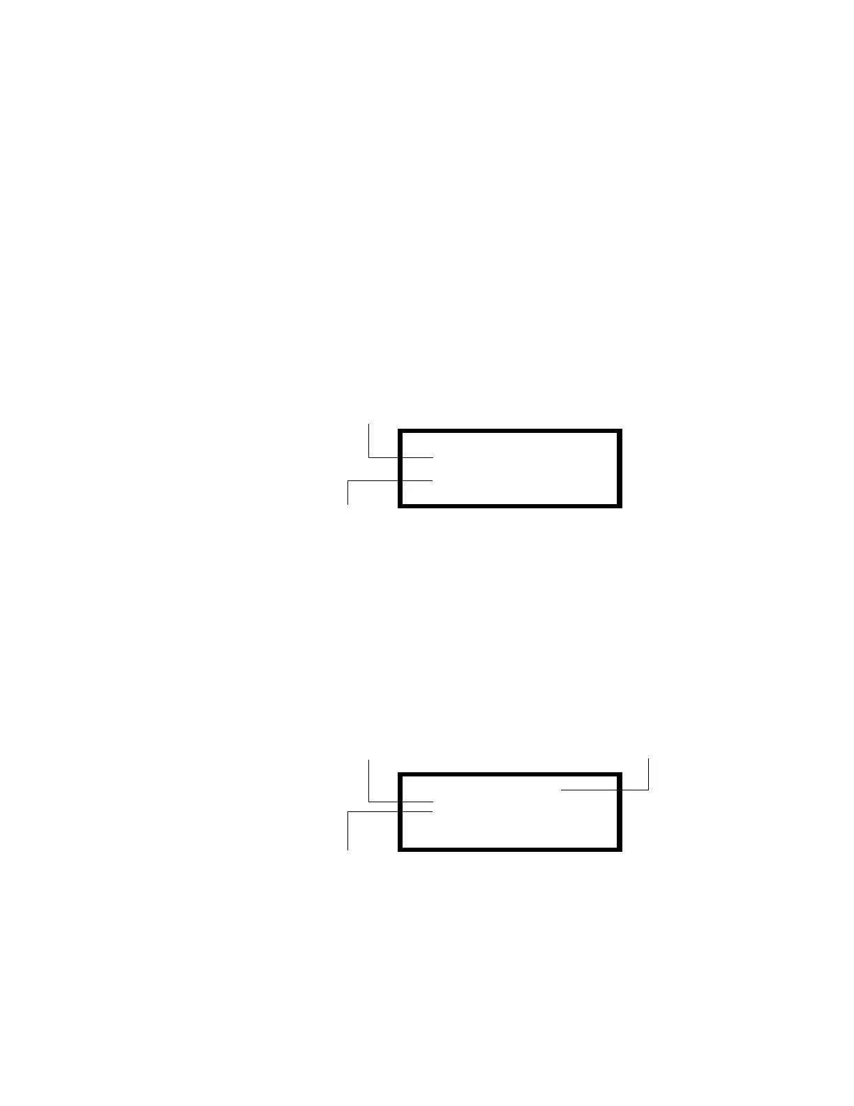
Figure 157 Sample of Action Level Pre-Alarm
Applications include computer rooms, electrical equipment rooms, and
telecommunication facilities where environments are clean and stable and early
warning is essential. Self-Optimizing mode is not recommended for applications (such
as cigarette smoking areas) where false smoke indications are present.
Programming
You can select Self-Optimizing for a photoelectric detector as follows:
1. From the Special Zone Change screen, select the 99=PREALM to display the
Pre-Alarm screen as shown in Figure 158.
Figure 158 Sample Pre-Alarm Screen with Self-Optimizing Settings
2. Set Pre-Alarm settings: ALERT=00 and ACTION=01 as shown in Figure 158.
3. Program each detector for which Pre-Alarm is desired. Figure 159 shows a sample
screen for a detector selected for Pre-Alarm. For detailed information on point
PRE-ALARM@SMOKE (PHOTO)
DETECTOR ADDRESS 03
ACTION:1.31/1.50%
03:02P 11/30/00 D03
Address of detector in Alarm
Date and time of occurrence
PRE-ALARM@ZONE@99
ALERT=00%@OF@ALARM
ACTION=01%@OF@ALARM
Alert=00% of Alarm
Action=01% of Alarm
Status banner for
Pre-Alarm Zone 99
 Loading...