Installation Expansion Power Supplies
IQ-301 PN 50036:F 10/29/2001 181
WARNING: Use extreme caution when working with the AVPS-24 or APS-6R—high
voltage and AC line-connected circuits are present in the AVPS-24 or APS-6R.
Turn off and remove all power sources. To reduce the risk of electric shock—make
sure to properly ground the AVPS-4R or APS-6R. Before connecting AC and DC
power, install the APS-6R cover.
.
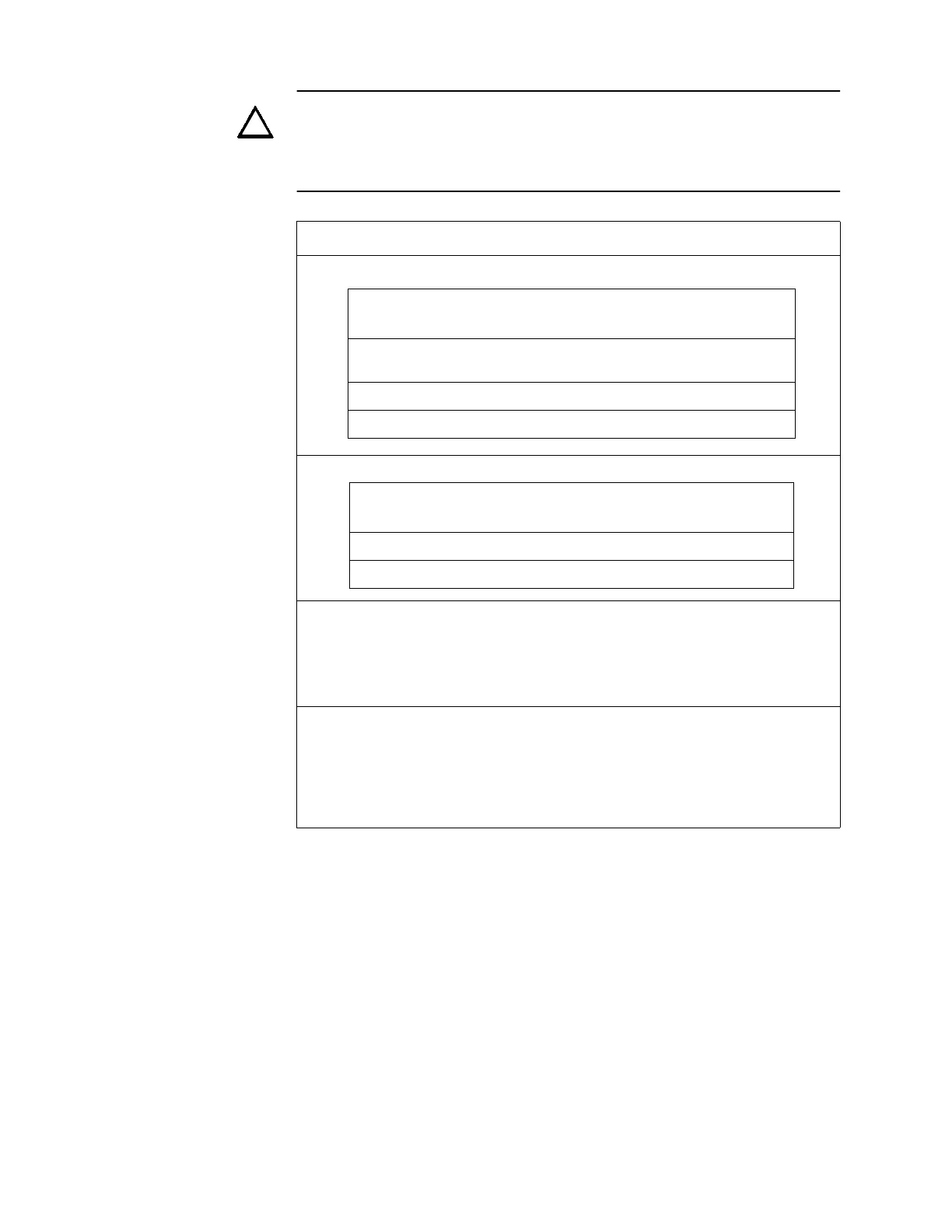
Table 68 AVPS-24/AVPS-24E Wiring Instructions
Step Action
1 Connect AC power as follows
2 Connect the battery as follows:
3 Connect the Power Harness to control panel NACs 3 and 4 as follows:
• Cut jumpers JP6 and JP 7 on the CPU board (Figure 164).
Plug the Power Harness (PN 71093) into plug J10 on the CPU board (Figure 164) as
follows:
• Connect J10 (–) to TB2 terminal 2 on the AVPS-24/AVPS-24E.
• Connect J10 (+) to TB2 terminal 1 on the AVPS-24/AVPS-24E.
4 Connect the Supervisory cable to the control panel as follows:
• Cut jumper JP3 on the CPU board (Figure 164)
• Plug the gray Supervisory Cable (PN 71033) into J11 with the wires exiting the
connector on top. Plug J11 is located in the bottom right center of the control panel
circuit board.
• Plug the other end of the Supervisory Cable into P1 on the AVPS-24 with the wires
exiting from the bottom (Figure 164).
!
Wire and Color
from
AVPS-24/AVPS-24E
to Control Panel
Earth Ground
(green)
TB1 terminal 6 TB7 terminal 3
AC Hot (black) TB1 terminal 5 TB7 terminal 1
AC Neutral (white) TB1 terminal 4 TB7 terminal 2
Wire and Color
from
AVPS-24/AVPS-24E
to Control Panel
Battery – (black) TB1 terminal 3 connector J3 (–)
Battery + (red) TB1 terminal 2 connector J3 (+)
 Loading...