This locator, through the analysis of the variations of special electric
signals, makes root apex location easier. If used together with a "file" (not
supplied) for manual treatment, it proves useful also to measure canal
length.
In addition to being used for manual detection with external wiring, the
locator can also perform live detection during root canal treatment. With
micromotor in ENDODONTIC mode and with suitable contra angles, the
locator uses the same file inserted in the canal as the active detection
probe.
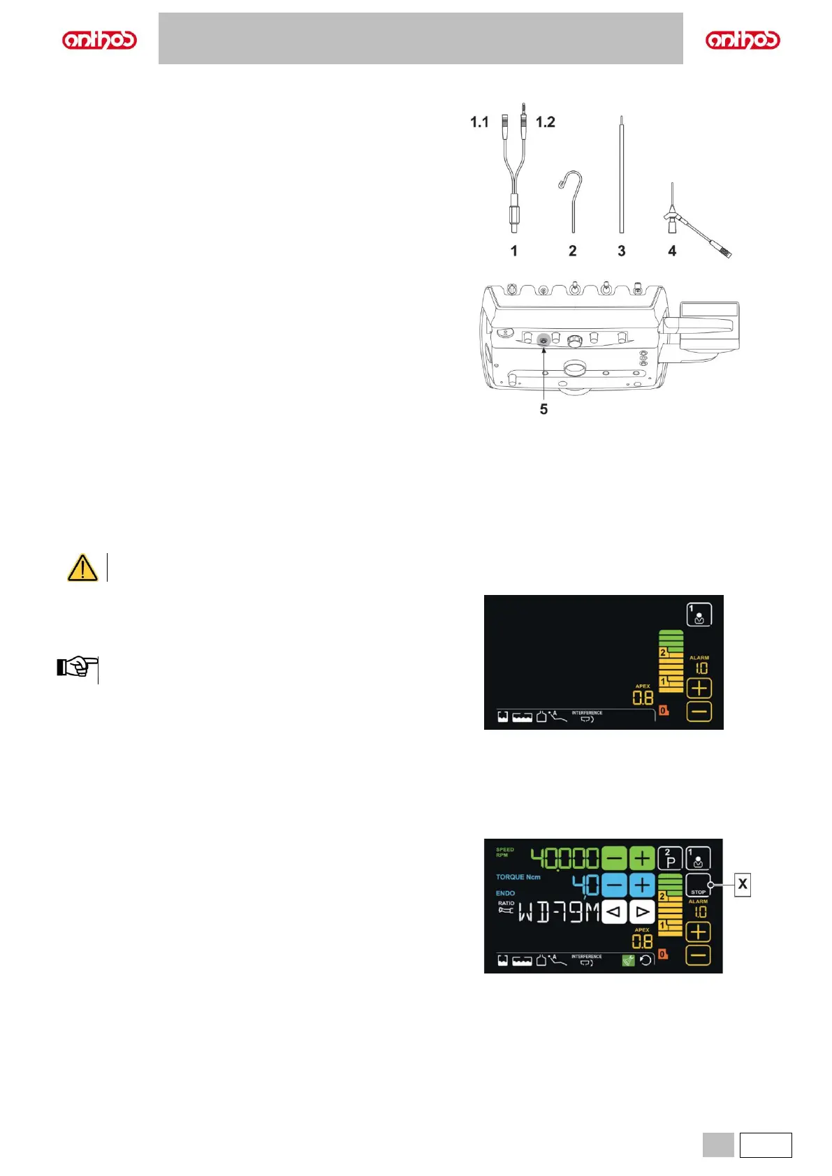
Component description.
1 APEX LOCATOR external wiring.
1.1 APEX LOCATOR external wiring - neutral pole.
1.2 APEX LOCATOR external wiring - active pole.
2 Hook-type electrode.
3 Probe.
4 APEX LOCATOR clip connecting tweezers.
5 APEX LOCATOR external wiring port.
Operation.
• On this dental unit, the locator is automatically activated upon external
wiring (1) insertion inside the special socket (5) positioned under
dentist's board.
Once enabled, the menu for trigger threshold setting appears on the
DISPLAY (see paragraph 5.1.1.17.).
• Electrode application:
- Connect hook-type electrode (2) to neutral pole (1.1) and position it
on patient's lip.
- Connect active pole (1.2) to file (not supplied) inserted inside the root
canal; connection to the file can be carried out through probe (3) or
through the special tweezers (4) or directly from the file inserted in the
canal through special handpieces.
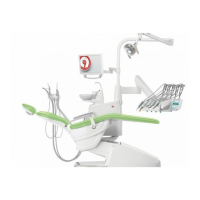
Indications on LCD Touch DISPLAY.
• The bargraph on DISPLAY right-hand side indicates file position
compared to apex. The numerical indications “1, 2" refer to the relative
distance between instrument and apex.
• The APEX icon displays the set trigger threshold.
The trigger threshold refers to the distance between instrument and
apex above which an audible signal - progressively increasing as
instrument gets closer to apex - is generated.
Set the time using the touch buttons "+" and "-".
Both graphic and numerical indications are constantly updated while file
is inserted inside canal.
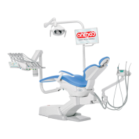
APEX LOCATOR combined with electric micromotor.
This locator can also be used in combination with the electric micromotor
when set to ENDO mode.
When the locator is enabled, if electric micromotor is extracted in ENDO
mode both the information relating to the micromotor and those relating to
locator (bargraph and APEX values) are shown at the same time on the
DISPLAY.
During electric micromotor operation, the keys are associated to
instrument functions, and locator trigger threshold cannot be edited but by
putting instrument back in place.
X APEX STOP enabled