1082 Smart Switch Operation Manual
CHA-1082-8000/11
__________________________________________________________________________________________________________
__________________________________________________________________________________________________________
Page 8 of 48
Standing by
Fast ID Beacon
LOW BATTERY!
PLUG IN DC PSU
DC IN RESET
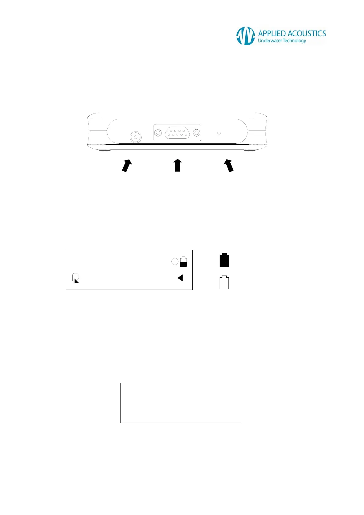
2.2 Connector Panel
A connector panel includes a DC input socket for the included 30VDC power supply unit, a 9-way
‘D’ socket for RS232 serial communication and beacon charging, and a reset button concealed
against accidental operation. Refer Section 10 Appendix for details.
Fig. 2
2.3 Internal Battery
The Smart Switch is powered from an internal rechargeable NiMH battery pack. With the Smart
Switch ‘awake’ and operational, the L.C.D. displays a battery icon at all times, representing the
current internal battery charge.
Fig. 3
Operational life is typically 2 days with constant use and with the backlight enabled. Standby life is
typically 5 months.
The Smart Switch internal battery is trickle charged at 40mA when the included 30VDC power
supply unit is inserted. When inserted, the Smart Switch is powered directly from the power supply
unit.
When the internal battery is near exhausted, the Smart Switch will constantly display a low battery
warning, as Fig. 4.
Fig. 4
The Smart Switch will be non-operable until the internal battery has been partially charged. Insert
the included 30VDC power supply unit. After a period of trickle charging, the Smart Switch will
reset and become operable.
DC INPUT
SOCKET
9-WAY ‘D’
SOCKET
RESET
BUTTON
BATTERY FULL CHARGE
BATTERY LOW CHARGE
9-WAY ‘D’
SOCKET