© Ikonix USA
14
Models
8505 8512 8520 8540
Standard Accessories
Interlock Disable Key (1505) X1
USB Cable X1
Shorting bar X1
Input/Output Terminal Protection Box X1
Power Cord (125Vac/10A) X1 - - -
Rack Mount (2U) X2 X2 X2 -
Rack Mount (4U) - - - X2
Handle for Rack (2U) X2 X2 X2 -
Why use the term “Counts”?
Associated Power Technologies publishes some specications using COUNTS which allows us to provide
a better indication of the tester’s capabilities across measurement ranges. A COUNT refers to the lowest
resolution of the display for a given measurement range. For example, if the resolution for voltage is 1V then
2 counts = 2V.
Measurement Considerations
*1) 8505, 8512, 8520VA: Input voltage is from 100V to 240V, maximum output power to resistive load, sine
wave, output frequency 25Hz to 1200Hz.
*2) At working voltage 100V / 200V.
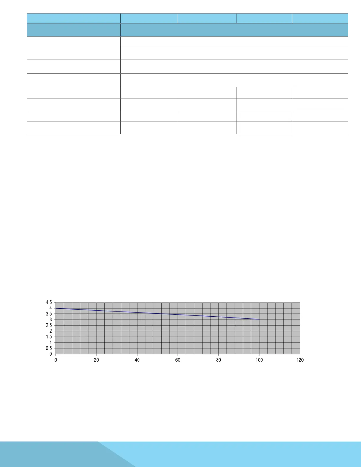
*3) The peak capacity of the instrument may vary from 3 to 4 times the max. rated current depending on the
voltage. Please refer the following chart:
*4 Maximum distortion is tested at 100 - 155V (155V Range) and 200 - 310V (310V Range) with maximum
current to a resistive load.
Crest Factor vs Output
Output Voltage %
Crest Factor