5.2.2 Connection to an Alternate Air Source
When connecting the actuation switch to an alternate air source, the
switch(es) should be wired according to Figures 24. and 25.,
depending on whether one or two Air Lockers will be installed in the
vehicle.
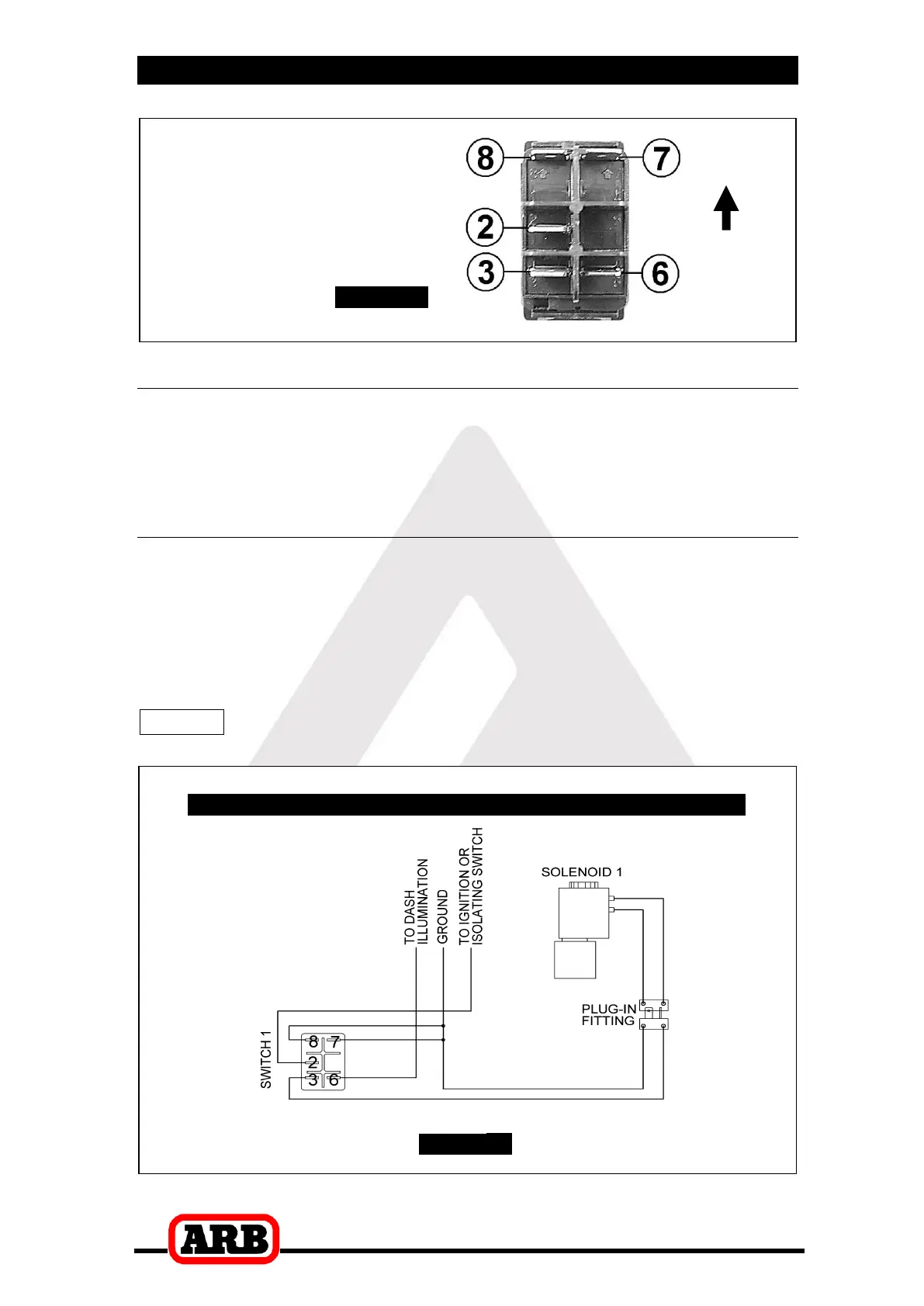
5.2.2.1 Single Air Locker System
If only one Air Locker is to be installed in the system, the switch and
solenoid should be wired according to Figure 24. regardless of
whether the Air Locker has been installed in the front or rear axle of
the vehicle.
Attach the appropriate switch cover (i.e., ‘FRONT’ or ‘REAR’) to the
switch.
NOTE : Refer to Figure 23. for the correct switch terminal
identification and switch orientation.
Figure